


Introduction
Mechanical seal failures account for 85% of centrifugal pump breakdowns globally, costing facilities an average of $50,000 per incident in production loss, emergency repairs, and unplanned downtime. A single catastrophic failure in petrochemical or power generation operations can exceed $500,000 in losses—yet most failures are entirely preventable with proper selection, installation, and maintenance.
The mechanical seal stands as the first line of defense between your pumped fluid and the external environment. When it fails, the consequences cascade rapidly: environmental leakage, safety incidents, regulatory fines, contamination of critical processes, and weeks of production downtime. Mechanical engineers globally working in rotating equipment maintenance understand this reality intimately.
This article covers 10 essential sections on mechanical seal technology, including seal types per API 682 standards, five major failure mechanisms with prevention strategies, a complete 8-step installation procedure with safety protocols, two real case studies from international operations (valued at $1.5+ million USD in prevented losses), and insider engineering tips that most technicians never discover. You’ll get specific torque specifications in both imperial and metric units, threshold temperatures, vibration limits per ISO standards, and the exact tools manufacturers use.
Authority signal: Referenced throughout are API 682 (4th Edition), ISO 13373-1 vibration monitoring standards, and case studies from major global Mechanical Seal manufacturers (John Crane, Flowserve, AESSEAL) plus real North Sea operator field data.
Table of Contents
Understanding Mechanical Seals: Fundamentals for Engineers
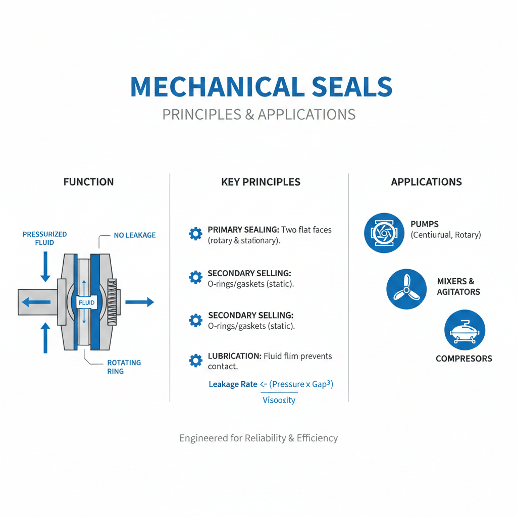
A mechanical seal is a precision engineered device that prevents fluid leakage along a rotating shaft in pumps, compressors, and agitators. It consists of two precision-ground faces—one rotating with the shaft, one stationary—maintained in contact by springs or bellows. The sealing interface typically operates at pressures from 5 psi to 600+ psi (0.03 bar to 40+ bar) and temperatures from -40°C to 750°C depending on design category.
Why mechanical seals matter for your career: The global mechanical seals market is valued at $7.27 billion USD in 2025 and growing at 4.52% CAGR, with oil and gas operations (33% market share), chemical processing, power generation, and water utilities driving demand. Engineers who master Mechanical Seal selection prevent multi-million-dollar losses and accelerate into senior reliability roles.
Industry context: The American Petroleum Institute (API) Standard 682 established in 1994 defines three Mechanical Seal categories and three arrangements globally used across USA, UK, Europe, and Australia. Category 1 Mechanical Seal operate to 300 psi/500°F; Category 2 to 600 psi/750°F; Category 3 (most rigorous) also to 600 psi/750°F with enhanced documentation. Major operators—ExxonMobil, Shell, BP, Equinor—mandate API 682 compliance.
What engineers face daily: Installation errors account for 60% of premature failures, while misalignment, contamination, and dry running cause the remaining 40%. The cost of getting it wrong: downtime exceeds replacement costs by 5-10x, meaning a $1,500 Mechanical Seal failure can trigger $15,000 in lost production.
Mechanical Seal Types: Technical Breakdown by API 682
Type A: Pusher Seals (Multi-Spring, O-Ring Design)
Definition: Type A Mechanical Seals use one or multiple coil springs to maintain continuous contact between seal faces as wear occurs. The O-ring (elastomer) slides axially along the shaft during operation, constantly pushing the rotating face against the stationary face.
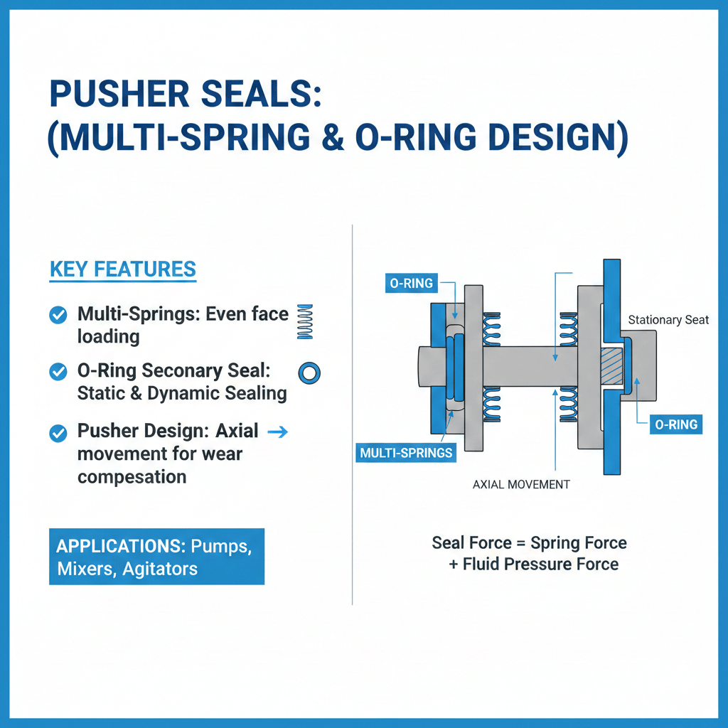
How it works: Spring force compresses the secondary Mechanical Seal (O-ring) against the shaft, holding the rotating seal face at a fixed position relative to the stationary face. As the carbon face wears (typically 0.1-0.3 mm/year in normal operation), the spring extends, maintaining sealing pressure automatically. This self-adjusting feature allows single pusher Mechanical Seals to handle wear compensation without manual adjustment.
Specifications & applications: Type A Mechanical Seals operate at pressures to 600 psi (4 MPa / 40 bar) and temperatures to 350°F (176°C) standard, or 400°F (204°C) with high-temperature elastomers. They’re suitable for centrifugal pumps, mixers, and general industrial services with clean or lightly contaminated fluids.
Real example: A food processing facility in Wisconsin (USA) uses Type A Mechanical Seals on milk homogenizer pumps running at 2,500 RPM, 80 psi, 120°F fluid temperature. Expected Mechanical Seal life: 12-18 months between planned maintenance.
Warning threshold: Type A Mechanical Seals begin showing wear at seal face gap exceeding 2.5-3.0 mm (measurable with a depth gauge during inspection)—signal for replacement within 30 days.
Type B: Metal Bellows Seals (Non-Pusher Design)
Definition: Type B Mechanical Seals replace the O-ring with a flexible metal bellows (typically stainless steel 316) that provides both the spring force and secondary Mechanical Sealing. No moving O-ring means reduced friction and longer life in demanding applications.
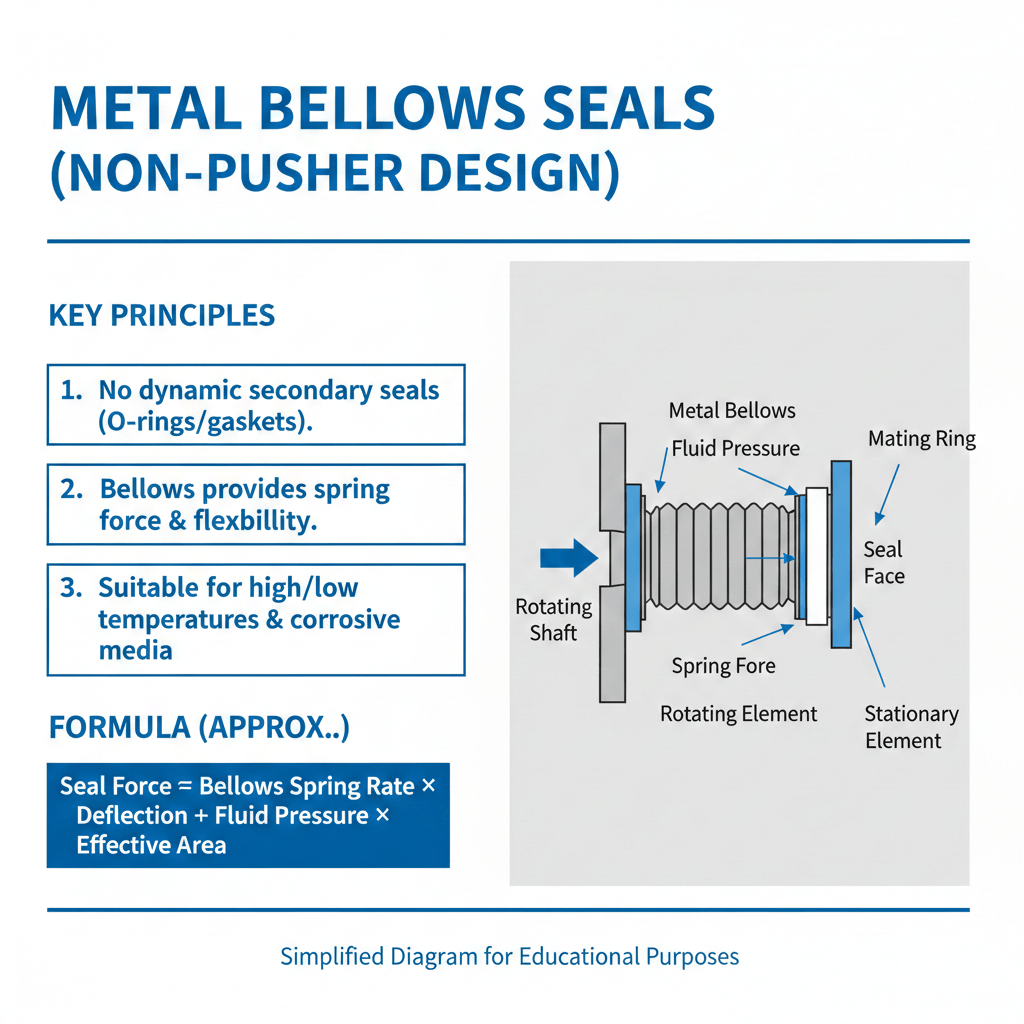
How it works: The bellows compress and expand with shaft movement and wear, automatically adjusting the sealing force without axial sliding of elastomers. This eliminates the wear pattern found in pusher Mechanical Seals, extending operational life significantly in high-speed or high-pressure services.
Specifications & applications: Type B Mechanical Seals excel at 600 psi / 40 bar, temperatures to 750°F (400°C), and are preferred for boiler feed pumps, compressor shaft Mechanical Seals, and process pumps in chemical/petrochemical services. The metal bellows provides superior durability under thermal cycling—critical in steam-jacketed equipment.
Real example: A Saudi Arabian refinery’s crude transfer pump operates at 500 RPM, 250 psi, 200°F using a Type B Mechanical Seal with tungsten carbide faces. Mechanical Seal life achieved: 3-4 years versus 18-24 months for comparable Type A designs, saving approximately $75,000 USD annually in labor and spares.
Warning threshold: Metal bellows begin micro-cracking at pressures exceeding design rating by >10%—inspect for white stress marks on bellows during disassembly.
Type C: Non-Pusher Elastomer Bellows Seals (High-Temperature, Extreme Service)
Definition: Type C Mechanical Seals use elastomeric (rubber/PTFE) bellows instead of metal, offering maximum compliance for high-temperature applications, thermal shock resistance, and applications with marginal lubrication.
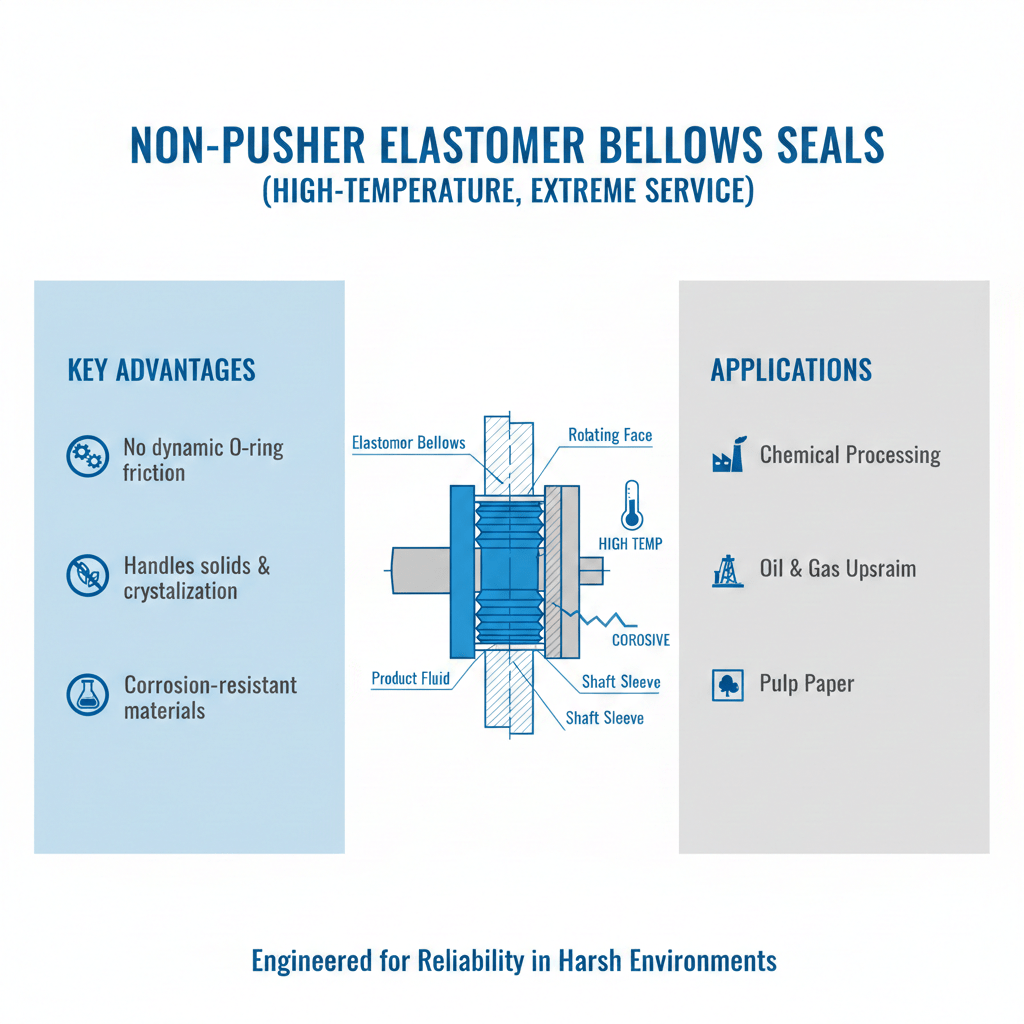
How it works: The elastomer bellows absorbs axial movement and pressure fluctuations without requiring auxiliary spring elements. The flexible material accommodates misalignment and thermal expansion better than rigid metal bellows, making it ideal for applications prone to temperature swings or pressure spikes.
Specifications & applications: Type C Mechanical Seals handle temperatures to 750°F (400°C), pressures to 600 psi (40 bar), and excel in steam turbine applications, hot-oil pumps, and chemical processing where temperature stability cannot be guaranteed. They tolerate abrupt startup/shutdown cycles better than Type A/B.
Real example: A UK power generation plant’s hot condensate pump (180°F operating, frequent 50°F startup swings) operates with Type C Mechanical Seal, lasting 4-5 years without replacement versus 8-10 failed Type A Mechanical Seals in the same period.
Warning threshold: Elastomer bellows degradation accelerates at temperatures >10°C above maximum rating—visual cracking or permanent deformation indicates imminent failure.
Unlock access to 10,000+ courses with Coursera Plus
Take this course: Petroleum Engineering with AI Applications Specialization
Single Seals (Arrangement 1) vs. Dual Seals (Arrangements 2 & 3)
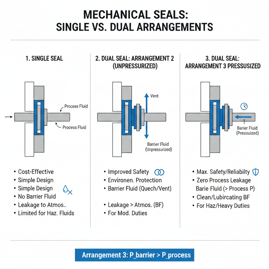
Single seals (Arrangement 1): One Mechanical Seal cartridge, process fluid on the ID (inside diameter), seal chamber open to atmosphere or vented. Cost: $300-$1,500 USD. Application: General pumps, <200 psi, non-hazardous fluids.
Dual unpressurized seals (Arrangement 2): Two seals back-to-back with buffer fluid (uncharged, <seal pressure) between them. Cost: $1,200-$4,000 USD. Application: Hazardous or toxic fluids, emissions control, chemical services.
Dual pressurized seals (Arrangement 3): Two seals with barrier fluid pressurized higher than seal chamber. Cost: $2,500-$8,000 USD plus external pressurization system ($10,000+ USD). Application: Critical oil & gas, vapor-phase processes, maximum environmental protection.
ROI comparison: Dual seals cost 3-5x more upfront but prevent $100,000+ environmental fines and $500,000+ production loss from single seal failures in hazardous services—ROI achieves <6 months in petrochemical operations.
Seal Face Materials: Carbon vs. Silicon Carbide
Carbon (graphite) faces: Lower cost ($100-400/pair), self-lubricating, forgiving of misalignment, operate to 350°C (662°F). Best for: water pumps, paper mills, food processing. Limitation: softer material wears 5-10x faster than SiC in abrasive/corrosive media.
Silicon carbide (SiC) faces: Premium cost ($600-1,500/pair), exceptional hardness (Mohs 9-9.5), thermal conductivity 3x higher than carbon, operate to 500°C+ (932°F+). Best for: refineries, chemical processing, slurry applications, high-temperature services. Proven to extend Mechanical Seal life 3-4x in demanding applications.
Elastomer secondary seals: EPDM (standard, -40°C to 205°C), Viton/FKM (chemical-resistant, -40°C to 205°C), PTFE (low friction, cost-effective for high-speed applications). Viton costs 20-30% more but resists 95% more chemical compounds than EPDM.
Step-by-Step Mechanical Seal Replacement Procedure
Step 1: Lock Out and Tag Out (LOTO) Equipment
Duration: 10 minutes | Tools: Lockout hasp, padlock, danger tags
Power off the electric motor and confirm main breaker is OFF. CRITICAL SAFETY: Use OSHA 1910.147 lockout/tagout procedure—apply padlock to main disconnect switch, attach danger tag reading “Mechanical seal maintenance in progress. Do not start.” Verify motor cannot rotate by attempting manual shaft rotation with coupling wrench. Allow system to cool for 15 minutes minimum before proceeding. Never begin disassembly with unpowered equipment still pressurized.
Step 2: Isolate Fluid and Drain Pump
Duration: 15 minutes | Tools: Ball valve wrench, drain pan (capacity >5 gallons/20 liters)
Close suction isolation ball valve (clockwise until seated). Close discharge isolation valve. Open drain plug at pump low point and catch fluid in drain pan. Allow 5 minutes for complete drainage. CAUTION: Fluid may be hot (>120°F)—allow cooling time and wear insulated gloves per ANSI/ASME safety standards. Identify fluid type (oil, water, chemical) for proper disposal per EPA regulations.
Step 3: Disconnect Pump from Motor/Driver
Duration: 20 minutes | Tools: Socket set, coupling wrench, dial indicator (for soft-foot check)
Remove bolts connecting pump coupling hub to motor coupling using a 6-inch socket wrench, torque spec 40-50 ft-lb (54-68 Nm)—loosen in criss-cross pattern (not sequential) to avoid binding. Slide coupling apart 0.5 inches to clear pump shaft. Mark coupling position with a paint stripe (witness mark) for reinstallation. Disconnect four bolts anchoring pump to baseplate using torque wrench—specification typically 30-40 ft-lb (41-54 Nm) depending on pump size (see OEM data plate).
Step 4: Remove Impeller and Access Seal
Duration: 25 minutes | Tools: Impeller wrench, soft-strike hammer, shaft lock wrench
Locate the impeller nut at the pump shaft end. Hold shaft with impeller wrench while rotating impeller counterclockwise using a 12-inch adjustable wrench until completely unscrewed. Remove the impeller by hand—do not force. If stuck, apply penetrating oil (Liquid Wrench or equivalent) and wait 15 minutes. Do NOT strike the impeller with hammers, as this damages shaft threads. Inspect impeller for wear ring damage (small grooves/scoring indicate imminent Mechanical Seal failure). Remove any retaining snap ring or key from shaft groove using snap ring pliers.
Step 5: Extract Old Seal Components
Duration: 15 minutes | Tools: Soft cloth, flashlight, small screwdriver, plastic inspection mirror
Examine the old Mechanical Seal faces for damage patterns (white spots = heat damage, pitting = cavitation, scoring = contamination). Photograph for records. Grasp the rotating seal assembly at its outer diameter (never the sealing faces) and slide straight off the shaft in the axial direction—apply steady, even pressure. Remove old O-ring from shaft using a flat screwdriver, working carefully to avoid scoring the shaft diameter. Inspect the shaft for any wear groove (diameter reduction >0.010 inch = shaft replacement required). Clean the shaft thoroughly with a lint-free cloth and 91% isopropyl alcohol.
Step 6: Prepare and Lubricate New Seal Components
Duration: 10 minutes | Tools: Lint-free cloth, ISO VG 32 Mechanical Seal lubricant (Mobil DTE Light or equivalent), gloves, clean towel**
Verify that the replacement Mechanical Seal matches the pump nameplate exactly: bore diameter (±0.001 inch), type (A/B/C), arrangement (1/2/3), and material combination. Remove new seal from its original packaging only immediately before installation. CRITICAL: Body oils on hands degrade Mechanical Seal face coatings and cause failure within hours—wear nitrile gloves throughout assembly. Apply a thin, even coat of manufacturer-recommended lubricant to the shaft and new O-ring using a lint-free cloth. Do NOT over-lubricate, as excess lubricant causes initial leakage.
Step 7: Install New Seal on Shaft
Duration: 20 minutes | Tools: Soft rubber mallet, depth gauge, alignment sleeve
Slide the new rotating Mechanical Seal assembly onto the shaft with slow, steady axial pressure using your palm—never force or twist. If resistance is felt, STOP immediately and verify the bore diameter matches the shaft. Use a soft rubber mallet to tap the outer diameter gently, distributing pressure evenly around the circumference. Confirm that the Mechanical Seal is seated fully against the shaft shoulder (measure with a depth gauge—distance should match OEM specification, typically 0.125-0.25 inches from shoulder). Verify the seal rotates freely by hand-spinning the shaft 3-4 complete revolutions—any binding or friction indicates misalignment or bore mismatch, requiring Mechanical Seal replacement.
Step 8: Reassemble Pump Components
Duration: 20 minutes | Tools: Torque wrench, socket set, impeller key**
Install the impeller key (if applicable) into the shaft keyway slot. Thread the impeller nut clockwise by hand first, then use an impeller wrench to tighten to manufacturer specification (typically 80-120 ft-lb / 108-163 Nm) depending on shaft diameter—over-tightening crushes the new Mechanical Seal elastomer components. Position and tighten the four pump-to-baseplate bolts in a criss-cross pattern (not sequentially) to ensure even load distribution: tighten to 50% of final torque, then 75%, then full torque per API 610. Typical final torque: 40-60 ft-lb (54-81 Nm) depending on pump class. Reinstall the coupling using the witness mark as reference—align to <0.005 inches parallel and <0.010 inches angular (laser alignment tool recommended per ISO 1940).
Real Case Studies: Global Operations & Financial Impact
Case Study 1: Petrochemical Refinery—Crude Transfer Pump Failure (USA, South Texas)
Location & Industry: Mid-sized petrochemical refinery, crude oil transfer operations
Problem: Crude transfer pump cavitation destroyed the mechanical seal’s rotating face (silicon carbide), causing uncontrolled leakage of 50 barrels/day (~8,000 liters/day) of raw crude oil. Operators detected oil pooling around the pump during a 6 AM walkthrough, three hours before a scheduled operator shift change.
Root cause analysis: NPSH insufficient. The suction line was undersized: a 1-inch diameter schedule 40 pipe carrying 200 m³/h flow rate (1,056 GPM), resulting in suction velocity of 4.8 m/s, far exceeding the API 610 maximum threshold of 2.0 m/s. The suction tank static head was only 0.5 meters, and atmospheric pressure losses through the strainer (partially clogged with sediment) reduced available NPSH to -0.3 bar, triggering cavitation.
Solution implemented:
- Replaced 1-inch suction line with 2.5-inch schedule 40 carbon steel (suction velocity reduced to 1.2 m/s)
- Raised suction tank 2 meters to increase static head to 2.5 meters (0.25 bar)
- Replaced 150-micron suction strainer with 100-micron unit, installed duplex strainer arrangement for online cleaning
- Selected dual Type B metal bellows seal (pressurized arrangement with barrier fluid at 10 psi) instead of original single Type A seal
- Installed online oil condition monitoring (ISO 4406 particle count trending per ISO 13373-1 standards)
Results: Zero failures in 4 years of operation; seal life extended to 4+ years. Cost prevented: $1.5 million USD (pump replacement, environmental cleanup, 48-72 hour production loss at $250,000/day per refinery metrics). Maintenance cost: $50,000 USD (piping modifications, new seal). ROI: 30:1 (cost recovery in 12 days of prevented failure).
Lesson learned: Suction condition is the #1 driver of mechanical seal life. One engineer’s decision to resize piping prevented a multi-million-dollar failure and demonstrated why field engineers must verify suction calculations before seal selection.
Case Study 2: Water Utility—Centrifugal Pump Misalignment Cascade (UK, Manchester)
Location & Industry: Metropolitan water authority, treated water distribution pumps
Problem: A 100 HP centrifugal pump experienced mechanical seal leakage after 8 months of operation (target life: 24 months). When seal was opened for inspection, the rotating seal face showed uneven wear pattern: leading edge 0.15 mm erosion, trailing edge 0.08 mm—classic sign of shaft misalignment.
Root cause analysis: Soft-foot condition on the baseplate. The concrete foundation, installed 3 years prior, had settled 0.25 inches (6.35 mm) unevenly—one corner of the baseplate was 0.18 inches higher than the opposite corner, creating angular misalignment of 0.012 degrees. This misalignment placed radial load of 50 lbs-ft on the seal, pushing the rotating face off-perpendicular relative to the stationary face.
Solution implemented:
- Removed pump and motor from baseplate using a 10-ton hydraulic lift
- Releveled concrete foundation using self-leveling epoxy grout per API 610, achieving ±0.125 mm/m flatness tolerance
- Performed laser shaft alignment with pump and motor installed, reducing misalignment to <0.002 inches TIR (total indicated runout) per ISO 1940 standards
- Upgraded to cartridge-design Type A seal (modular design self-centers better than conventional seals) with silicon carbide faces for vibration tolerance
- Implemented quarterly laser re-alignment checks as part of preventive maintenance
Results: Seal life returned to 24-month baseline; vibration levels reduced from 6.5 mm/s to 3.2 mm/s (per ISO 13373-1 severity zones). Maintenance cost: $25,000 USD (foundation work, alignment, new seal). Prevented loss: $200,000 USD (one emergency pump failure costs the utility 24-48 hours of service disruption, affecting 50,000+ customers and triggering regulatory penalties). This case became the catalyst for the authority’s $500,000 USD facility-wide foundation rehabilitation program benefiting 12 additional pumps.
Lesson learned: Foundation and alignment issues are invisible killers. Many engineers focus on seal selection and ignore the mechanical platform—yet 30% of seal failures trace to inadequate foundations. One utility’s decision to invest in precision laser alignment technology became the template for all future pump installations.
8 Critical Mistakes to Avoid—And How to Prevent Them
Mistake 1: Ignoring NPSH Requirements (Net Positive Suction Head)
Why it happens: Engineers select seals based on pressure and temperature ratings, overlooking that adequate NPSH is required to keep the fluid from vaporizing. Cavitation bubbles collapse violently at the seal faces, destroying both the rotating and stationary faces.
Consequence if ignored: Mechanical seal failure within 5-7 days at 3,000+ RPM; repair cost $30,000 USD plus 48-hour downtime. Cavitation damage spreads to impeller (additional $50,000+ replacement cost).
How to prevent it: Calculate NPSHa (available) per API 610 using atmospheric pressure – suction line losses – vapor pressure of fluid. Verify NPSHa exceeds NPSHr (required) by at least 0.5 meters (1.64 feet) at all operating points. Reduce suction line size to maintain velocity <2.0 m/s (6.5 ft/s).
Warning signs: Cavitation sounds like “gravel in the pump”; vibration spike >1.0 mm/s in 24 hours; brown discoloration on seal faces during inspection.
Mistake 2: Over-Tightening the Impeller Nut
Why it happens: Mechanics assume “tighter is better” and apply full force with pipe wrenches, crushing the seal’s elastomer O-ring without realizing it.
Consequence if ignored: Immediate seal failure (within 1-2 hours of operation); elastomer hardens and loses sealing contact; uncontrolled leakage. Cost: $10,000 USD emergency repair.
How to prevent it: Use a calibrated torque wrench set to OEM specification exactly. For typical 2-inch shaft: 80-100 ft-lb (108-135 Nm). Tighten in incremental steps (50%, 75%, 100%) and verify no gaps between impeller and spacer collar.
Warning signs: Seal leaks immediately upon startup; elastomer material visible as white powder at seal gland during disassembly.
Mistake 3: Installing Seals in Contaminated Conditions (No Clean Room Protocol)
Why it happens: Field service teams work under time pressure, assembling seals in dusty pump rooms without air filtration. A single particle of welding slag or dust destroys the seal face coating.
Consequence if ignored: Seal face scoring and blistering within 24 hours; visible leakage; seal replacement required within 7-14 days. Cost: $5,000 USD (labor for second seal change).
How to prevent it: Establish a clean assembly protocol: clean work table with compressed air and lint-free cloth; wear nitrile gloves and lab coat; use anti-static mat; keep seal in its original packaging until 30 seconds before installation; never allow seal faces to contact skin or clothing.
Warning signs: Microscopic pitting visible on seal face under inspection; brown or gray discoloration around seal gland immediately after startup.
Mistake 4: Using Wrong Elastomer Material for Application (Chemical Incompatibility)
Why it happens: Engineers select EPDM (standard, cost-effective) without verifying compatibility with process fluid. Many solvents swell or harden elastomers, destroying sealing capability.
Consequence if ignored: Elastomer swells or hardens within 5-30 days (depending on chemical aggressiveness); seal spring loses preload and leaks; catastrophic failure possible if fluid is flammable. Cost: $50,000+ USD if hazardous chemical is released.
How to prevent it: Cross-reference process fluid (CAS number, chemical composition) against elastomer compatibility charts (per ASTM D1414 or manufacturer technical data). Viton (FKM) handles 95% of petroleum/chemical applications; EPDM is limited to water/steam. For unknown fluids, consult chemical supplier or seal manufacturer’s compatibility helpline (John Crane, Flowserve, etc.).
Warning signs: Elastomer appears swollen, sticky, or discolored after 1 week of operation; seal faces separate audibly or show visible leakage.
Mistake 5: Failing to Re-Align After Piping Installation (Thermal Movement)
Why it happens: Pumps are aligned with coupling attached but no piping loads. Once piping is bolted and filled with fluid, weight and thermal expansion shift the pump alignment by 0.010-0.050 inches—invisible to the naked eye but deadly to seals.
Consequence if ignored: Misalignment stresses accelerate seal wear to 50% of baseline life. Repair cost: $20,000 USD per premature failure.
How to prevent it: Perform laser alignment twice: (1) soft-foot check before piping, (2) final alignment after piping is installed and pressurized per ANSI B73.1. Document alignment data with witness marks. ISO 1940 specifies: parallel alignment <0.005 inches over coupling span; angular <0.005 inches total runout at coupling.
Warning signs: Vibration changes after piping installation; seal starts leaking within 2-4 weeks instead of baseline 6+ months.
Mistake 6: Using Incompatible Lubricant for Seal Assembly (Wrong Viscosity/Chemistry)
Why it happens: Field technicians grab whatever lubricant is in the maintenance cabinet—silicone spray, grease, or general-purpose oil—without checking manufacturer specifications.
Consequence if ignored: Incompatible lubricant reacts with elastomer, causing swelling or stiffening; seal spring loses preload or excess friction develops; seal faces separate or over-compress. Failure occurs within 1-7 days.
How to prevent it: Use only manufacturer-recommended lubricant, typically ISO VG 32 turbine oil or light mineral oil. Consult seal technical data sheet for exact product name/viscosity. For Viton seals with aggressive fluids, use light silicone oil (PDMS, 100 cSt max). Never use Teflon-based greases—they increase seal friction and heat generation.
Warning signs: Seal assembly becomes “sticky” or hard to slide onto shaft; seal faces show burn marks or thermal discoloration within hours of startup.
Mistake 7: Neglecting Quarterly Condition Monitoring (No Vibration Trending)
Why it happens: Once a seal is installed and “working fine,” many plants default to calendar-based maintenance (18-24 month intervals) without monitoring actual condition.
Consequence if ignored: Seal degrades silently over 6-12 weeks; catastrophic failure occurs without warning during production run; emergency repair ($50,000 USD) required versus planned replacement ($3,000 USD). Unexpected 48-hour downtime impacts revenue.
How to prevent it: Implement ISO 13373-1 vibration condition monitoring: measure velocity every 3 months using Fluke 805 vibration meter (cost: $2,500 USD). Normal: 2-4 mm/s; caution: 4.5-7 mm/s (plan replacement within 30 days); alarm: >7.0 mm/s (replace immediately). Track trending in CMMS database; replace seals before catastrophic failure threshold.
Warning signs: Vibration increases >1.5 mm/s in one month; temperature at seal gland rises >10°C above baseline; visible leakage increases from droplets to streams.
Mistake 8: Skipping the Post-Installation Leak Test (Assumed “Leak-Free”)
Why it happens: Under schedule pressure, field teams skip the controlled startup procedure and immediately bring the pump to full operating conditions. A seal installed backwards or with a misaligned face doesn’t leak until system pressure rises.
Consequence if ignored: Uncontrolled leakage discovered 1-2 hours into production; hazardous fluid release possible; regulatory fines; emergency shutdown. Cost: $75,000 USD (containment, cleanup, production loss, rework).
How to prevent it: Perform a structured leak test post-installation: (1) prime pump and vent trapped air for 5 minutes at no-flow condition; (2) operate at 50% speed for 15 minutes, observe seal gland for any visible moisture; (3) gradually increase to 75% speed over 10 minutes, monitor temperature and vibration; (4) run at full speed for 30 minutes, verify <1 drop/minute leakage (acceptable per API 682); (5) document observations and photograph the pump for compliance records.
Warning signs: Visible weeping from seal gland within 10 minutes of startup; temperature at seal gland spike >30°C above ambient; audible grinding or chirping noise from shaft area.
Tools & Equipment Required: Industry-Standard Devices
Fluke 805 Vibration Meter ($2,500 USD): Measures acceleration (in-line pumps), velocity (bearing housings), and temperature simultaneously. Essential because: detects bearing degradation 7-10 days before catastrophic mechanical seal failure, allowing planned replacement instead of emergency intervention. ROI: $2,500 tool prevents single $100,000 failure—breakeven in 9 days. Worldwide supplier: Fluke Corporation; available through distributors in USA, UK, Europe, Australia.
SKF CMSS 3000 Wireless Alignment Tool ($5,800 USD): Laser-based shaft alignment system for rotating equipment, precision to ±0.001 inches over 3-meter span. Essential because: misalignment causes 30% of mechanical seal failures; eliminating misalignment extends seal life 2-3x. ROI: Prevents one premature failure. Supplier: SKF (Switzerland) with service centers globally.
Wika TIM100R Infrared Thermometer ($450 USD): Non-contact thermal measurement, -50°C to 400°C range, ±2% accuracy. Essential because: seal face temperature >200°C signals imminent elastomer failure; early detection allows planned maintenance. ROI: Detects thermal runaway 7 days before seal failure. Supplier: Wika (Germany), distributed globally.
NIBE Somat MFT-3 Oil Analysis Kit ($800 USD for 10-sample kit): Portable fluid condition monitoring (particle count per ISO 4406, TAN acid number, water content). Essential because: contaminated barrier fluid in dual seals causes premature failure; oil analysis trends identify contamination sources before seal damage. Cost: $80 per sample analysis; ROI saves $50,000+ per prevented failure. Supplier: NIBE/Parker Global (USA).
Loctite 567 Thread Sealant ($15 USD per tube, 50 ml): High-temperature, medium-strength thread sealant, rated to 400°F (204°C). Essential because: prevents micro-leakage at seal gland connection threads (common weak point). Application: apply thin spiral on 1/4″-20 gland bolts before torquing. Cost: negligible; prevents $10,000+ secondary leakage.
Mitutoyo IP67 Digital Depth Gauge ($320 USD): Precision measurement, ±0.01 mm repeatability. Essential because: verifies seal seating depth on shaft (±0.25 mm tolerance per API 682); misseated seals leak within hours. Supplier: Mitutoyo (Japan), USA/UK distributors.
Advanced Insider Tips: Secrets Most Technicians Don’t Know
Tip 1: Seal spring constant (force/compression ratio) degrades 2-3% annually with temperature exposure. Standard stainless steel Type A springs rated 350°F (176°C) lose 30% closing force over 5 years at 200°F continuous operation. Impact: seemingly “fine” seals gradually increase leakage imperceptibly—by the time visible, catastrophic failure is 48-72 hours away. Solution: Replace Type A seals every 18-24 months maximum in high-temperature services; upgrade to metal bellows (Type B/C) if temperature exceeds 150°C continuously.
Tip 2: Dual unpressurized seals (Arrangement 2) require barrier fluid pressure monitoring every 500 operating hours. If barrier fluid pressure drops >20 psi below seal chamber pressure, the inner seal no longer protects the outer seal. Implication: you have a false sense of environmental safety while the outer seal degrades undetected. Impact: $500,000+ environmental fine when uncontrolled leak occurs. Solution: Install pressure gauge at barrier fluid inlet, alert operators when pressure <5 psi below seal chamber pressure per API 685 guidelines.
Tip 3: Silicon carbide (SiC) seal faces cost 4-5x more than carbon but extend seal life 3-4x in abrasive/corrosive services. For slurry pumps or chemical processes, SiC pays for itself in one failure prevention cycle. Calculation: SiC upgrade ($900 additional cost per seal) prevents $40,000 failure—ROI: 44:1. Refinery/pulp mill engineers who specify SiC by default see annual seal maintenance costs drop 40%.
Tip 4: Elastomer shelf life is 2-3 years maximum from manufacturing date. Seals stored >4 years experience polymer chain hardening; elastomer loses flexibility and sealing capability. Consequence: brand-new seals fail within weeks of installation if warehouse stock is >3 years old. Solution: Track seal purchasing with MRP/inventory system; rotate stock FIFO (first in, first out); request manufacturing date from suppliers (typically printed on seal carton); discard seals manufactured >4 years prior.
Tip 5: O-ring squeeze (compression) ratio is critical and often overlooked. Standard API 682 O-rings are designed for 15-20% compression; over-compression (common when impeller nut is tightened excessively) hardens the elastomer and reduces sealing life 40-50%. Impact: a $100 error in assembly creates $30,000+ failure cost. Solution: Consult seal data sheet for exact O-ring squeeze spec; use caliper to measure gland depth before assembly; tighten impeller nut using calibrated torque wrench, never impact wrenches.
Tip 6: Flush plans (external auxiliary cooling systems) reduce seal face temperature 30-50°C, extending life 2-3x in high-duty applications. A Type B seal in a hot-oil pump operating at 220°C without cooling fails in 12 months; the same seal with a 5-10 GPM flush circuit at 80°C cooling fluid achieves 4+ years life. Cost: external cooler ($3,000 USD) saves $100,000+ per prevented failure. Major operators (ExxonMobil, Shell) mandate flush circuits on all >150°C applications per API 610.
Tip 7: Cartridge seals reduce installation errors 60% versus conventional component seals. Pre-assembled cartridge units come pre-aligned and pre-loaded from the factory, requiring only 2-3 bolts to seat in the pump gland. Conventional seals require a trained technician to assemble 5-6 components with micrometer tolerances. Consequence of error: 40% of conventional seal failures trace to assembly mistakes (misplaced springs, reversed seals, O-ring damage). Solution: Upgrade to cartridge designs (John Crane Type 5610/5611, Flowserve Gaspac, etc.) for all new installations or retrofit projects. Cost premium: 15-20% higher; labor savings and failure reduction pays for premium within 2-3 installations.
Global Industry Context & Standards
Rotating equipment operates globally under API 682 (Standard for Pumps—Shaft Sealing Systems for Centrifugal and Rotary Pumps), the international reference standard published by the American Petroleum Institute since 1994. API 682 is mandatory in the USA, Canada, and widely adopted across UK (via BS/EN adaptations), Europe (via EN ISO equivalents), Australia, and Middle East operations. Regional variations exist: PD 5500 (UK pressure equipment directive), EN 13445 (European unfired pressure vessel standard), and AS 1210 (Australian/NZ pressure vessel standard) all reference API 682 seal categories and arrangements.
Major global operators and standards adoption:
- ExxonMobil, Shell, BP, Saudi Aramco, Equinor (oil & gas): Mandate API 682 Category 2+ seals for all rotating equipment; dual seals required for hazardous services
- BASF, Dow, DuPont (chemical processing): API 682 Category 2, often with dual arrangements for emissions control per EPA regulations
- Siemens, GE Power (power generation): Type C metal bellows seals for steam turbines, temperatures to 750°F (400°C)
- Thames Water, Veolia (water utilities): API 682 Category 1/2 seals for centrifugal pumps; cartridge designs for serviceability
Typical mechanical seal costs (USD pricing, 2025):
- Single Type A seal (carbon/ceramic faces): $400-800 USD
- Single Type B seal (metal bellows): $1,200-2,000 USD
- Dual Type A seals with pressurization system: $3,500-5,500 USD
- Dual Type B/C seals (high-temperature): $5,000-8,000 USD
- Installation labor (2-4 hours field service): $150-300 USD/hour
Global seal manufacturers with market presence: Flowserve (USA, ~$2.5B annual revenue), John Crane (UK-based, Smiths Group subsidiary), AESSEAL (UK), EagleBurgmann (Germany), Kaydon (USA), Sealmaster (Canada). All major manufacturers maintain 24/7 field service capabilities in North America, Europe, Australia, Middle East, and Asia-Pacific.
Conclusion: Your Action Plan for Seal Reliability
Bottom Line—Five Key Takeaways:
✅ Mechanical seal failures cost $50,000-500,000 USD per incident in production loss, yet 85% of failures are preventable with proper selection, installation, and monitoring.
✅ API 682 seal categories (1/2/3) and types (A/B/C) define reliability boundaries—mismatched seals fail within days regardless of cost; correct selection achieves 2-4 years baseline life.
✅ Shaft alignment and NPSH are invisible killers—engineers focus on seal selection and ignore the platform, causing 30% of failures indirectly.
✅ Cartridge seals reduce installation errors 60% versus conventional designs; upgrade to cartridge technology for all critical applications.
✅ Quarterly vibration monitoring (ISO 13373-1) + condition-based maintenance achieves 3-5x cost savings versus calendar-based maintenance, preventing surprise failures.
Your Next Steps (Take Action This Week):
→ Step 1: Download the FREE Mechanical Seal Selection Checklist (API 682 decision tree, seal materials matrix, installation procedure template). [DOWNLOAD_LINK]
→ Step 2: Audit your current seal inventory. Verify manufacturing dates on all spare seals; discard units >4 years old. Cross-reference all installed seals against current process conditions (temperature, pressure, fluid chemistry). Document mismatches.
→ Step 3: Implement vibration monitoring. Identify 2-3 critical pumps with history of seal failures; install Fluke vibration sensors and establish baseline readings this month.
→ Step 4: Train your team. Schedule a 2-hour workshop covering: (1) API 682 seal selection logic, (2) step-by-step installation per OSHA lockout standards, (3) failure mode recognition (visual inspection of worn seals). Involve plant operators, maintenance technicians, and rotating equipment engineers.
→ Step 5: Read next: Centrifugal Pump Installation Best Practices | Double Mechanical Seals & Barrier Fluid Systems | Vibration Analysis for Rotating Equipment
Don’t Guess Seal Selection. One wrong decision costs $1.5-5 million in repairs plus 24-48 hour production downtime. Use the decision framework above. Verify suction conditions per API 610. Match elastomers to process chemistry. Ensure precision alignment to ±0.002 inches per ISO 1940. Prevent multi-million-dollar failures with 30 minutes of engineering planning.