


Introduction {#introduction}
Centrifugal pumps dominate fluid handling in construction, moving water for dewatering, concrete mixing, and site operations with unmatched efficiency. Poor centrifugal pump design and performance leads to delays, equipment failure, and cost overruns—issues plaguing 30% of construction projects due to cavitation or improper sizing. Engineers must grasp impeller dynamics, performance curves, and system integration to optimize flow rates up to 200 m³/hr at heads of 10-50m.
This masterclass delivers actionable insights into centrifugal pump design and performance, from fundamentals to advanced CFD simulations. Construction teams rely on these pumps for dewatering flooded sites, where improper selection causes 20-40% efficiency losses and premature wear. Expect step-by-step calculations, checklists, real-world case studies, and software recommendations to implement immediately. Global market growth to USD 48B by 2033 underscores their critical role in infrastructure.
Mastery ensures pumps operate at best efficiency point (BEP), slashing energy costs by 15-25% and extending lifespan. Dive into formulas like affinity laws and NPSH to avoid cavitation, a failure mode in 25% of industrial pumps.
Table of Contents
Why Centrifugal Pumps Matter in Construction {#construction-importance}
Construction sites demand reliable fluid movement for dewatering, slurry handling, and pressure washing. Centrifugal pump design and performance directly impacts project timelines—standing water halts excavation, risking foundation instability and safety hazards. In urban projects, pumps remove groundwater at rates of 100-500 GPM, preventing delays costing $10K+ per day.
Market data shows centrifugal pumps hold 46.9% share in Asia-Pacific construction, driven by infrastructure booms. Dewatering variants like trash pumps handle debris-laden water, essential for highway and high-rise builds. Energy efficiency matters: optimized designs cut power use by 20%, vital amid rising electricity costs.
Safety improves with proper performance—vibration from off-BEP operation causes 15% of site accidents. For concrete mixing, high-pressure delivery ensures uniform hydration, reducing defects by 30%. Teams selecting via performance curves avoid oversizing, which wastes 10-15% energy.
Fundamental Concepts {#fundamentals}
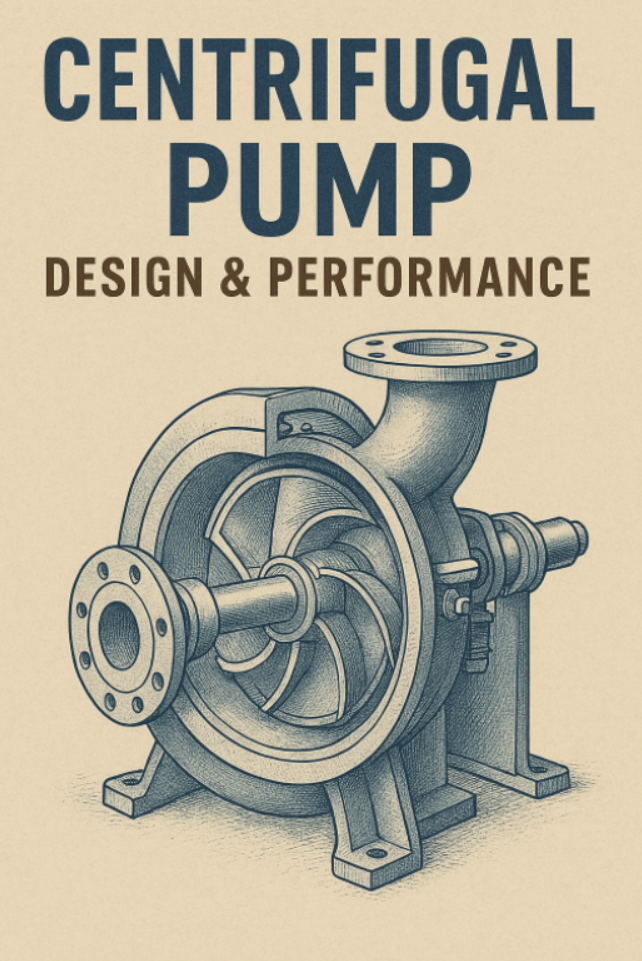
Centrifugal pumps convert rotational energy to hydrodynamic energy via impeller rotation, creating centrifugal force that pushes fluid outward. Key components include impeller, casing, shaft, bearings, and seals. Fluid enters axially, accelerates radially, and exits under pressure.
Head (H) measures energy imparted per unit weight, in meters: static, friction, and velocity heads sum to total dynamic head (TDH). Flow rate (Q) in m³/hr depends on impeller diameter (D) and speed (N in RPM). Net Positive Suction Head (NPSH) prevents cavitation: NPSHA > NPSHR by 1-2m margin.
Efficiency (η) peaks at BEP, typically 70-85% for construction pumps. Power (P) formula:
P=ηρgQH
where ρ is density, g=9.81 m/s². Specific speed (Ns) classifies designs: low for high-head, high for large flows.
| Parameter | Symbol | Unit | Construction Typical |
|---|---|---|---|
| Flow Rate | Q | m³/hr | 50-300 |
| Head | H | m | 10-50 |
| Speed | N | RPM | 1450-2900 |
| Efficiency | η | % | 70-85 |
Impeller Design Principles {#impeller-design}
Blade Types and Angles {#blade-types}
Impellers feature radial, mixed-flow, or axial blades. Construction favors semi-open radial for solids handling. Inlet angle β1=15-25°, outlet β2=20-40° optimize velocity.
Diameter and Width Calculation {#impeller-calc}
Eye diameter D1=0.3-0.5D2; outlet D2 from specific speed. Width b2=Q/(π D2 V_u), V_u=π D2 N/60.
Checklist: Impeller Sizing
- Calculate Ns = N √Q / H^{3/4}
- Select D2 for 80-120% BEP flow
- Verify NPSHR < NPSHA
- Balance to G2.5 grade
Casing and Volute Design {#casing-design}
Volute casings convert velocity to pressure via increasing cross-section. Worm or diffuser types; construction uses single volute for cost. Tongue angle 10-15° minimizes recirculation.
Diffuser vanes (6-8) guide flow in high-head designs. Wear rings maintain 0.3-0.5mm clearance.
Performance Curves Explained {#performance-curves}
Curves plot Q vs H (downward), efficiency (bell-shaped), power (upward), NPSHR (rising). BEP at peak η, 70-90% Qmax. System curve intersects for operating point.
Reading Steps:
Key Design Formulas {#design-formulas}
Affinity laws predict changes:
Q2=Q1N1N2,H2=H1(N1N2)2,P2=P1(N1N2)3
Flow: Q=πD2b2Vu2
BHP: BHP=3960ηQHSG (US units).
Practical Design Methodologies {#practical-methods}
Step 1: Requirement Analysis {#req-analysis}
Determine Q, H_total = H_static + H_friction + H_velocity. Friction: Hazen-Williams or Darcy.
Step 2: Preliminary Sizing {#prelim-sizing}
Ns=1000-4000 for single-stage. Select series via catalogs.
Step 3: Detailed Calculation {#detailed-calc}
Impeller: D2 = √(g H / (u2 tanβ2)), u2=π N D2/60.
Step-by-Step Pump Selection Checklist
- Measure Q and H_system
- Add 10% safety to H
- Choose pump curve matching 80-110% BEP
- Check NPSH, power
- Verify materials (ductile iron for construction)
Step 4: System Integration {#system-int}
Advanced Applications {#advanced-apps}
High-pressure multistage for grouting (5-10 stages, 100m+ head). Variable frequency drives (VFD) adjust speed, saving 20-50% energy. Slurry pumps with 10% solids tolerance for site mud.
CFD optimizes via ANSYS CFX, predicting 5-10% η gains.
Tools and Software {#tools-software}
Pump-Flo selects from databases, generates curves. ANSYS CFX simulates impeller flow. CicloSoft sizes with motor matching. Free: Engineering Toolbox affinity calculator.
| Software | Key Feature | Cost |
|---|---|---|
| ANSYS CFX | CFD analysis | $$$ |
| Pump-Flo | Catalog selection | $$ |
| CicloSoft | Hydraulic calc | $ |
Common Mistakes and Solutions {#common-mistakes}
- Off-BEP Operation: Causes vibration. Solution: Throttle or VFD to BEP.
- Cavitation: Low NPSHA. Solution: Elevate pump, enlarge suction.
- Oversizing: 15% energy waste. Solution: Match system curve.
- Poor Suction: Air locks. Solution: Vertical inlet >60°.
- Seal Failure: Dry run. Solution: Flush plan 11/32.
- Pipe Strain: Misalignment. Solution: Support piping.
Troubleshooting Checklist
- Vibration? Check BEP, alignment
- Low flow? Suction clog, impeller wear
- Overheat? Low flow, bad bearings
Case Study 1: Construction Dewatering {#case1}
Urban high-rise site flooded post-rain. Selected 150 m³/hr, 20m head trash pump. Dewatered 500m³ in 3 days, avoiding $50K delay. Post-install, η=78% at BEP. Challenge: Debris—solved with 10mm solids passage.
Case Study 2: Refinery Cooling Tower {#case2}
Axial split pumps vibrated at 64% flow. Added flow straightener, trimmed impeller—vibration dropped 70%, MTBF tripled.
Worked Example: Pump Sizing {#worked-example}
Design for Q=200 m³/hr, H=10m, N=1480 RPM, water.
- Ns = 1480 √(200/3600) / 10^{0.75} ≈ 220 (radial impeller)
- D2 ≈ 0.4m (est.)
- BHP = (10009.81200/360010)/(0.751000) ≈ 15 kW
- Affinity: Halve N to 740 RPM → Q=100 m³/hr, H=2.5m
Verify curve intersection.
FAQ {#faq}
Q1: How to calculate centrifugal pump head?
A: H_total = H_static + k Q² (friction). k from pipe data.
Q2: What causes cavitation?
A: NPSHA < NPSHR. Elevate source, reduce T.
Q3: Read performance curve?
A: Intersect system curve with H-Q; check η, NPSHR.
Q4: Affinity laws for VFD?
A: Q∝N, H∝N², P∝N³.
Q5: Best impeller for solids?
A: Semi-open radial, 8% solids max.
Q6: Troubleshoot low flow?
A: Check suction, wear, valves.
Q7: Efficiency improvement?
A: Operate BEP, trim impeller.
Q8: Multistage vs single?
A: Multistage for H>50m.
Conclusion {#conclusion}
Centrifugal pump design and performance optimization transforms construction efficiency, cutting costs 20% via proper sizing, BEP operation, and NPSH management. Key takeaways: Use affinity laws for scaling, read curves for selection, avoid cavitation with checklists. Real cases prove dewatering savings and vibration fixes.
Implement now: Audit site pumps against system curves, integrate VFDs, simulate with CFX. Link to [hitvapk.com/hvac-pumps-guide] for HVAC integration. Explore [hitvapk.com/pump-maintenance] best practices. Download free curve templates at [hitvapk.com/resources]. Your team gains reliability—start with NPSH calc today. CTA: Subscribe for pump webinars.
Related Articles
- Embedded Hardware and Operating Systems
- Electrodynamics: In-depth Solutions for Maxwell’s Equations
- Electrodynamics: Electric and Magnetic Fields
- Electrical Power Distribution
- Electric Power Systems