


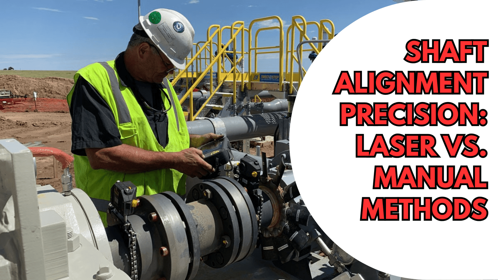
Shaft Alignment Precision for mechanical engineers managing centrifugal pumps, compressors, turbines, and motors in rotating equipment operations, alignment isn’t a box-ticking exercise—it’s an operational imperative. The difference between a machine aligned to ±0.05 mm (API 610 standard) and one aligned to ±0.5 mm can mean the difference between five years of trouble-free operation and catastrophic failure within weeks. Modern laser Shaft Alignment Precision have revolutionized how engineers approach this critical maintenance task, delivering micron-level precision in minutes rather than hours. Yet traditional dial indicator methods remain industry-standard in many plants, despite their limitations.
This technical guide examines both Shaft Alignment methodologies, breaks down the physics behind precision, provides field-proven procedures with real-world numbers, and reveals why one approach delivers exponentially better reliability outcomes. You’ll learn tolerance specifications per API 610, ISO 1940-1, and ISO 13373-1 standards; examine case studies from USA, UK, and European petrochemical operations; and discover the advanced tips that separate master technicians from average maintenance crews.
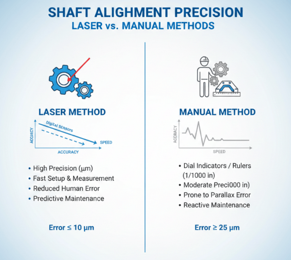
Table of Contents
Fundamentals: Why Shaft Alignment Determines Machine Life
Shaft Alignment is the process of positioning two or more rotating shafts so their centerlines are collinear (perfectly aligned along the same axis) during operation. When shafts aren’t collinear, they introduce parallel misalignment (offset: shafts parallel but displaced) and angular misalignment (shafts at an angle to each other). These conditions seem trivial—often just a few thousandths of an inch—but they create profound mechanical consequences.
Misalignment forces shafts to deflect during rotation, increasing bending stress on the rotor and generating excessive radial loads on bearings. A bearing designed to handle 50 kN of purely radial load will see an additional 15-20 kN of side-loading under just 0.1 mm offset misalignment. This cascading load accelerates bearing wear, shortens service life from 50,000+ operating hours to just 5,000-10,000 hours, and triggers catastrophic failure within weeks of initial deterioration.
Energy consumption rises dramatically. Misaligned machinery requires 1-15% more electrical power to achieve the same output because the motor must overcome friction from rubbing surfaces and deflection forces. For a 35 HP pump running 24/7 at $0.06/kWh, this translates to $2,000-$12,000 in wasted electricity annually per machine—or $600,000+ across a facility of 100 pumps. Precision Shaft Alignment cuts this waste to near-zero through friction minimization.
The mechanical seal—a 6-8 inch precision component managing pressure between pump impeller and external environment—fails three times faster under misalignment. Seal faces experience uneven contact pressure, micro-leaks develop, lubricant breaks down, and failure occurs 40-60% sooner than design life. Global industry data shows seal replacement costs of $5,000-$15,000 per incident, including parts, labor, and production loss.
API 610 (the standard for centrifugal pumps in petroleum services) specifies Shaft Alignment tolerances of ±0.002 inches (0.05 mm) offset and ±0.0001 in/in (0.1 mm per 100 mm) angular misalignment at cold (ambient) condition. ISO 1940-1 balance standards and ISO 13373-1 vibration diagnostic standards enforce these limits globally. Compliance isn’t optional—it’s written into equipment warranties and regulatory requirements across USA (ASME), UK (PD 5500), and European (EN) jurisdictions.
Technical Breakdown: Shaft Alignment Laser vs. Manual Alignment Methods
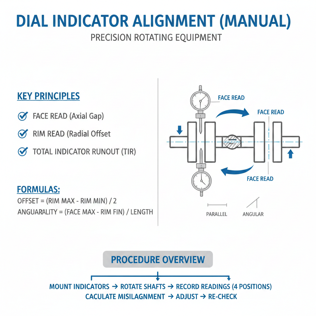
Method 1: Dial Indicator Alignment (Manual)
The reverse dial indicator method dates to the 1950s but remains prevalent in industrial plants worldwide. Two precision dial indicators (graduated in 0.001-inch increments) mount perpendicular to the coupling via magnetic or clamp brackets. As shafts rotate through 0°, 90°, 180°, and 270° positions, technicians record readings showing shaft runout (total indicated runout or TIR). Calculations using graph paper or formulas determine offset and angular misalignment; technicians then shim or move the motor/pump to correct toward zero.
Advantages: Equipment costs only $1,000-$2,500 (Accushim HA-2 kit: $2,205 USD). No power required. Familiar methodology taught in apprenticeships for decades.
Limitations: Heavily dependent on technician skill and experience. Backlash in dial indicator mechanisms introduces ±0.002-0.003 inch uncertainty. Gravity causes shaft sag between measurement points, distorting readings. Measurement takes 1.5-3 hours per Shaft Alignment. Documentation is manual and subjective. Repeatability is poor—different technicians achieve different results on the same equipment (typically ±0.005-0.010 inches variation). In fast-moving industrial environments, this method struggles with time constraints.
Method 2: Laser Shaft Alignment (Modern)
Laser Shaft Alignment systems mount a laser transmitter on one shaft and a precision detector on the opposing shaft. As the shaft rotates, the laser beam sweeps across multi-axis position-sensitive detectors (PSDs). Software calculates misalignment in real-time with micron-level resolution (±0.0001 inches typical accuracy). Systems like PRÜFTECHNIK Rotalign Ultra, SKF TKSA 41, and Ludeca Easy-Laser XT capture 100-300+ measurement points per rotation, filter noise automatically, and provide digital reports with before/after graphs.
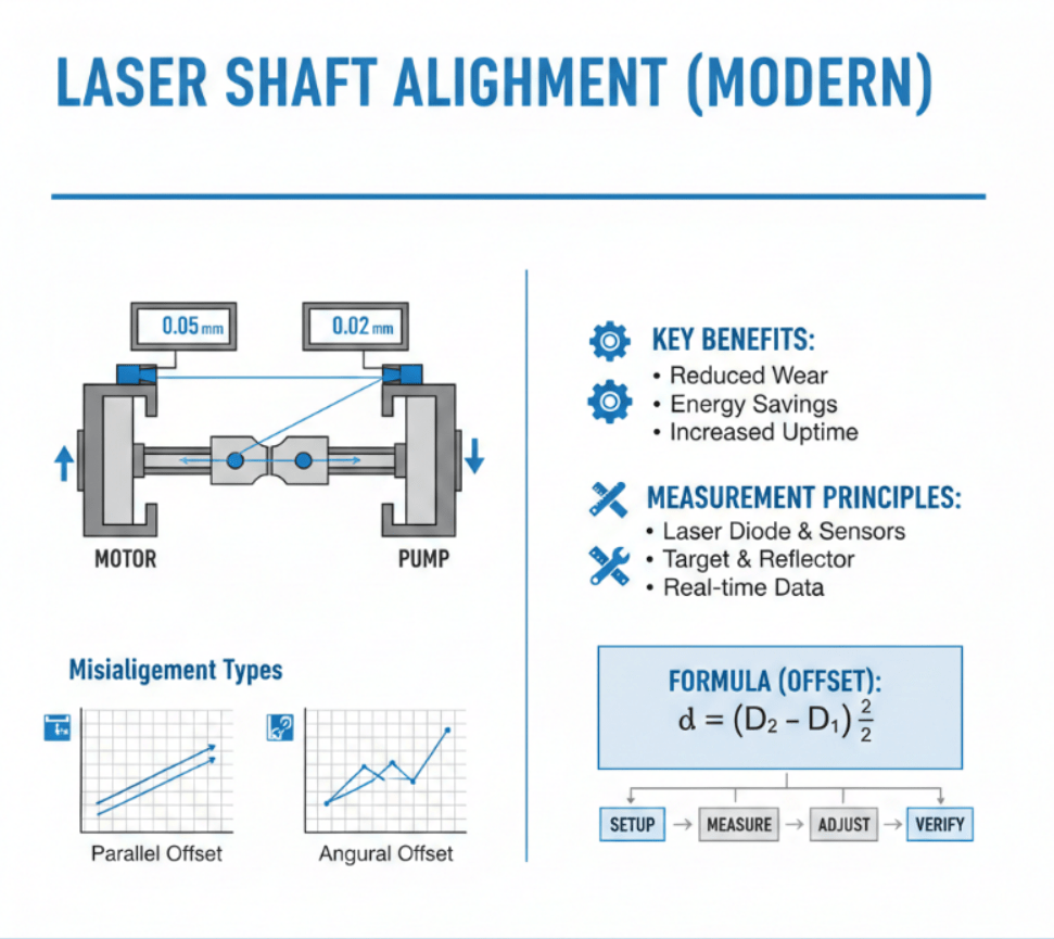
Advanced systems integrate intelligent alignment software with situational awareness: they detect coupling backlash, measure thermal growth via live trending, monitor environmental vibration, and provide step-by-step correction guidance displayed on tablets or smartphones. Single-laser technology (vs. older dual-laser systems) improves setup speed and eliminates the Shaft Alignment challenges of dual-beam crossover.
Advantages: Measurement accuracy of ±0.0001 inches (±0.0025 mm). Alignment typically completed in 20-45 minutes. Real-time feedback eliminates guesswork: technicians watch numbers change as they shim/move machines, stopping when readings hit target. Digital documentation with color photos, measurement tables, and PDF reports ensures regulatory compliance and creates a permanent record. Repeatability excellent—same technician, different days, achieves identical results within 0.001 inches. Intuitive software requires minimal training compared to dial indicator mastery.
Limitations: Higher capital cost ($3,500-$8,000 USD for basic systems; $15,000-$25,000 for advanced multi-machine systems with vibration modules). Requires power supply. Sunlight can affect optical sensors (though modern inductive sensors eliminate this). Requires environmental vibration <0.02 g acceleration in some high-precision applications.
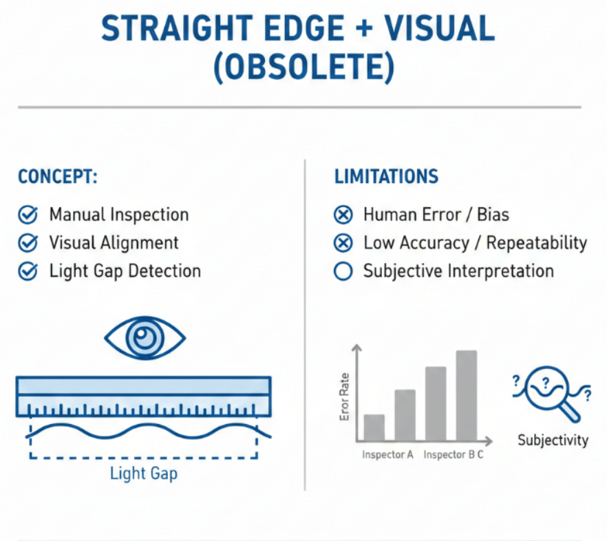
Method 3: Straight Edge + Visual (Obsolete)
This outdated method relied on physical straightedges and visual judgment. Modern engineering standards (API 610, ISO 13373-1) no longer permit this approach for machinery critical to operations or safety.
Step-by-Step Laser Shaft Alignment Procedure Per ISO Standards
Time Required: 45 minutes for standard horizontal pump-motor coupling (additional 15-20 min for thermal trending or soft-foot checks).
Safety: Lock out and tag out (LOTO) both motor and pump per OSHA 1910.147 before beginning. Verify no residual pressure in pump discharge. Ensure all rotating elements are stopped and will not rotate during measurement. Use proper personal protective equipment (PPE) including hard hat and safety glasses.
Tools Required: Laser Shaft Alignment system (PRÜFTECHNIK, Ludeca, SKF, or equivalent), measuring tape (metric/imperial), ball level, feeler gauges (0.002-0.010 inch), soft foot shim kit, jacking bolts or adjustable feet, torque wrench (wrench sizes per OEM manual).
Step 1: Preliminary Setup and Soft Foot Check (8 minutes)
Remove coupling guard. Ensure both machines sit level on mounting feet via ball level placed on horizontal surfaces. Check for soft foot by placing feeler gauge under each foot while pushing down on motor frame with 100 lb force—all four feet should contact mounting surface without deflection gaps >0.002 inches. If soft foot detected, insert shims under feet until all feet sit firmly.
Step 2: Mount Laser Alignment Brackets (7 minutes)
Attach laser transmitter bracket to one shaft (typically motor) using provided V-blocks and clamps per manufacturer guidance. Position transmitter brackets 90° apart from coupling face. Mount detector unit on opposing shaft (pump), ensuring detector optic window faces transmitter directly. Verify bracket security by hand-tugging—zero movement permitted.
Step 3: Initialize Measurement and Establish Baseline (10 minutes)
Power laser system. Enter machine foot dimensions (distance from coupling to front feet, front-to-back foot spacing) via touchscreen or tablet app. Rotate both shafts by hand together through at least two complete revolutions to ensure smooth rotation and eliminate any mechanical stiction. The system will automatically capture baseline misalignment data and display offset and angular misalignment values in real-time on the display unit screen.
Step 4: Analyze Misalignment Data (3 minutes)
The system displays results in both metric and imperial units: Offset misalignment (typically shown in mils or mm at the coupling face—example: “0.087 inches offset” means shafts are displaced 0.087 inches perpendicular to their nominal centerline). Angular misalignment (shown as mils per inch of shaft span—example: “0.045 mils/inch” means 0.045 thousandths of an inch change per inch of separation). Compare readings to machine OEM tolerance or API 610 standard: acceptable offset ≤0.002 inches, angular ≤0.0001 in/in.
Step 5: Correct Vertical Misalignment Via Shims (12 minutes)
If vertical misalignment exists, the system will recommend shim values at front and rear feet (example: “Add 0.010 inch shim at front foot, 0.005 inch at rear foot”). Loosen all four motor mounting bolts by hand only—do NOT use power tools yet. Insert shims beneath feet, ensuring shim edges don’t protrude beyond foot width (creates edge-loading stress). Retighten bolts by hand. Rotate shafts manually and verify laser readings decrease. Repeat shim adjustments iteratively until readings approach zero target.
Step 6: Correct Horizontal Misalignment Via Motor Movement (10 minutes)
If horizontal offset remains, use jacking bolts positioned under motor feet (typically 2 bolts on opposite corners) to slide motor side-to-side. Advance jacking bolts by ½-turn increments. Rotate shafts and check laser display for horizontal movement value. Continue incrementally until horizontal reading is within 0.001 inches of target. This step requires patience—rushing often over-corrects and requires multiple iterations.
Step 7: Final Verification and Tightening (5 minutes)
Once all readings converge toward target (typically within 0.001-0.002 inches), tighten all mounting bolts sequentially in an X-pattern (diagonal opposite bolts) to the torque specified in the motor nameplate or OEM manual (typically 150-450 ft-lb depending on bolt size). Apply torque gradually: tighten to 50% specified torque on first pass, then full torque on second pass. Tighten jacking bolts completely to prevent movement during coupling installation.
After tightening, immediately rotate shafts by hand three full revolutions and re-measure Shaft Alignment readings. Tightening bolts sometimes introduces 0.001-0.003 inches of movement due to baseplate settling. If readings remain within 0.002 inches of target, proceed to Step 8. If readings exceed tolerance, loosen bolts and repeat shim adjustment.
Step 8: Coupling Installation and Final Check (8 minutes)
Install flexible coupling (if previously removed) per OEM instructions, verifying coupling gap meets specifications (typically 0.250-0.375 inches). Once coupling is fully installed, verify shaft runout with dial indicator at coupling hub face—runout should be <0.002 inches TIR per API 610. If runout exceeds tolerance, the shaft may be bent and requires replacement.
Worked Example: A 100 HP centrifugal pump motor (1800 RPM, 2 pole) shows initial laser readings of offset = 0.087 inches, angular = 0.062 mils/inch. API 610 target for 1800 RPM: offset ≤0.002 in, angular ≤0.001 in/in. Distance between motor feet: 24 inches.
Technician measures shim values: front foot 0.010 inches, rear foot 0.005 inches (calculated to split the 0.062 mil/inch angular error across the 24-inch span). After inserting shims and jacking motor, readings improve to offset = 0.001 inch, angular = 0.0008 in/in—within tolerance. After tightening bolts and re-measuring, final readings show offset = 0.0015 inches, angular = 0.0009 in/in. Alignment complete.
Global Case Studies: Laser Shaft AlignmentShaft Alignment Impact Across Industries
Case Study 1: Crude Oil Transfer Pump Failure—South Texas Petrochemical Refinery, USA
A major petroleum refiner (ExxonMobil-scale facility, >100,000 barrel/day throughput) experienced rapid coupling cavitation and bearing failure in a 5,000 GPM, 1,200 HP crude transfer pump after 18 months of service. Internal inspection revealed pump bearings worn beyond tolerance, mechanical seal faces pitted, and impeller cavitation damage across 40% of blade surfaces.
Root cause analysis: The pump had been aligned using dial indicators by a contract technician with limited experience. Initial Shaft Alignment tolerances were documented as “within 0.010 inches offset”—five times worse than API 610 requirements. Over 18 months, thermal growth, piping strain, and foundation settling gradually worsened misalignment to 0.015+ inches offset.
Solution: Facility invested in a PRÜFTECHNIK Rotalign Ultra laser system ($18,000 USD). Technicians re-aligned the replacement pump to ±0.0015 inches offset, ±0.0008 in/in angular using laser guidance. Thermal growth trending was recorded: pump showed 0.008 inches of cold-to-hot growth over the first 48 hours of operation; Shaft Alignment remained within tolerance throughout thermal transient.
Results: No bearing failures in subsequent 7 years of operation (now >60,000 operating hours). Mechanical seal lasted 8.2 years (vs. previous 1.5-year cycle). Energy consumption post-alignment measured 2.8% lower than pre-alignment baseline, saving $21,000 annually in electricity costs on this single machine.
Lesson learned: Misalignment tolerance errors compound over years. Precision laser Shaft Alignment plus thermal growth monitoring prevents multi-million-dollar failures.
Case Study 2: UK Chemical Processing Facility—Multiple Pump Fleet Alignment Initiative
A UK-based fine chemicals manufacturer (Yorkshire) operated 47 centrifugal pumps across three process plants. Maintenance records showed 18-24 unplanned pump shutdowns annually, averaging 6-12 hours downtime per incident. Average repair cost per failure: £18,000 (approximately $23,000 USD) including spare parts, contract technician labor, and production loss.
Before initiative: Facility relied on dial indicator Shaft Alignment, performed every 2-3 years or “when equipment acts up.” Average measured misalignment at inspection: 0.008-0.015 inches offset—well beyond tolerance.
Solution: Facility purchased three laser Shaft Alignment systems (SKF TKSA 41, £4,500 each) and trained internal technicians in laser methods per ISO 13373-1 standards. All 47 pumps were re-aligned within 6 weeks. Quarterly re-alignment checks were scheduled as preventive maintenance.
Results: First-year unplanned downtime dropped to 4 incidents (83% reduction). Average downtime per incident fell to 2 hours due to faster laser-guided corrections. Annual maintenance cost reduction: £108,000 (approximately $140,000 USD). ROI on laser system investment: 12 weeks. By Year 3, facility achieved zero unplanned pump shutdowns related to misalignment.
Lesson learned: Systematic laser-based Shaft Alignment programs (not one-off corrections) create measurable reliability gains and return capital investment in months, not years.
Common Mistakes That Destroy Equipment and Waste Budget
Mistake 1: Aligning at Cold Temperature, Ignoring Thermal Growth
Many technicians align equipment in ambient conditions (68-72°F) without accounting for thermal expansion during operation. A steel shaft expanding 0.1-0.15 mm from ambient to operating temperature (e.g., 35°C rise in pumped fluid) will shift misalignment by an equivalent amount. Equipment aligned perfectly at cold conditions degrades to 0.005+ inches misalignment within hours of startup.
Prevention: Use laser system’s thermal growth trending function (enabled on PRÜFTECHNIK and Ludeca systems). Measure Shaft Alignment at ambient, then continuously monitor shaft movement during 8-12 hour run-up until thermal steady-state is reached. Document the cold-to-hot offset and create “hot alignment” targets that account for this growth. For critical machinery, perform final check under operating conditions.
Warning sign: Vibration increases noticeably 4-6 hours after pump startup, then stabilizes—suggesting thermal misalignment. Measure immediately before thermal growth masks the diagnosis.
Mistake 2: Over-Shimming Without Checking Soft Foot
Technicians sometimes “correct” misalignment by stacking excessive shims under one or two feet, unaware that soft foot is actually the root cause. The machine frame flexes during assembly, creating apparent misalignment that shims can’t fix permanently.
Prevention: Always perform soft foot check first (feeler gauge test per Step 1 above). If soft foot >0.002 inches exists, correct it before measuring Shaft Alignment. Use parallel shims, never stepped shims, to maintain uniform foot contact.
Warning sign: Alignment readings drift continuously even after tightening bolts. Indicator fluctuates ±0.002 inches with no clear trend.
Mistake 3: Loose Coupling Backlash Misinterpreted as Misalignment
Flexible couplings develop internal wear and backlash (0.005-0.015 inches) over years. Worn couplings create apparent shaft movement when rotated by hand, confusing technicians into “correcting” misalignment that doesn’t actually exist.
Prevention: Verify coupling backlash before Shaft Alignment. Grab the pump shaft with a pipe wrench and try to rock it side-to-side—record the total movement. If movement exceeds 0.010 inches, coupling is worn and should be replaced. Modern laser systems with intelligent backlash detection automatically filter this noise.
Warning sign: Dial indicator readings vary by 0.010+ inches depending on rotation direction or speed. Laser system reports “measurement quality poor.”
Mistake 4: Not Documenting Baseline or Accepting Vague Tolerances
Many facilities lack written Shaft Alignment records. Technicians perform alignment verbally (“looks good”) without recording offset/angular values, creating no evidence of compliance with API 610. If a bearing fails weeks later, root cause analysis is impossible.
Prevention: Require digital or printed before/after Shaft Alignment reports for every alignment job. Include photographic evidence of laser display readings, machine dimensions, shim values used, and date/technician name. File reports in equipment maintenance database (CMMS software like Maximo or SAP Plant Maintenance).
Warning sign: Facility managers can’t answer “When was this pump last aligned and to what tolerances?”
Mistake 5: Assuming Dial Indicators and Laser Systems Are Equivalent
Some engineers believe dial indicator results are “close enough” to laser results, missing the 10-100x accuracy difference. A dial indicator Shaft Alignment may report “0.003 inches offset,” but the true error is often 0.008-0.015 inches due to measurement uncertainty and technician experience variance.
Prevention: Reserve dial indicators for field diagnostics only (checking if soft foot exists, verifying coupling runout <0.005 inches). Use laser systems for actual Shaft Alignment work on equipment where failure cost exceeds $50,000 or where bearing life expectancy is critical.
Warning sign: Bearing failures recur every 12-24 months despite “alignment maintenance.” Compare your historical failure rate to industry benchmarks (should be <1 failure per 10,000 operating hours after precision alignment).
Tools & Equipment: Investment for Precision
PRÜFTECHNIK Rotalign Ultra IS Laser Alignment System (Germany) – $22,500 USD
Industry’s most advanced system. Features include continuous sweep measurement (intelliSWEEP), environmental vibration monitoring, live thermal trend tracking, and multi-coupling simultaneous measurement. Bluetooth wireless capability. Detectors handle “any amount of misalignment” (InfiniRange) including severely misaligned equipment. Built-in inclinometer detects coupling backlash automatically. ROI: Cost is recovered in 2-3 prevented bearing failures (each bearing replacement = $8,000-$15,000 cost including parts and downtime). For high-duty-cycle pump operations, pays for itself within 12 months.
SKF TKSA 41 Laser Shaft Alignment Tool (Sweden) – $7,277 USD
Wireless, touch-screen driven system. Large detector units enable measurement under challenging lighting conditions and vibration. Ideal for mid-size industrial operations. Training time minimal (2-4 hours). 5-year warranty. ROI: Comparable to Rotalign—recovered within first 2-3 alignment jobs on critical equipment.
Ludeca Easy-Laser XT770 (USA) – $24,000 USD
Flagship system with 360° live adjustment: users can adjust machines at any sensor position (not restricted to preset measurement points). Integrated thermal camera for IR temperature profiling before/after Shaft Alignment. Soft foot and twist-measurement capabilities. IP67 rated (fully submersible). Preferred for harsh environments and multi-machine trains. ROI identical to Rotalign Ultra.
Fluke 805 Vibration Meter – $2,720 USD
Complements laser Shaft Alignment by measuring equipment vibration before/after corrections. Captures bearing condition via Crest Factor+ technology (proprietary algorithm). Temperature measurement via IR sensor. Essential for verifying that laser alignment actually reduced vibration per ISO 10816 standards (target <2.8 mm/s RMS for unrestricted operation). ROI: Prevents repeat alignment attempts by providing objective vibration baseline.
Accushim HA-2 Dial Indicator Kit (USA) – $2,205 USD
Budget option for small operations. Precision dial indicators (0.001 inch gradations), V-blocks, magnetic bases, and clamps. Suitable for training, field diagnostics, and low-speed backup methods. Limitation: accuracy ±0.003 inches, requires 2-4 hours per Shaft Alignment, technician-dependent.
Extech IR267 Thermal Camera – $799 USD
Non-contact infrared camera for bearing hotspot detection. Identifies temperature asymmetry indicating misalignment or lubrication failure. Useful for remote measurements during operation without shutdown. Complements laser alignment by showing real-world heat generation.
Advanced Insider Tips: What Master Technicians Know
Tip 1: Thermal Growth Prediction Saves Hot-Restart Downtime
Many facilities run equipment, let it reach thermal steady-state, then shut down and repeat the next day. Each cold-start to hot-operating-state transition creates 0.1-0.2 mm of shaft movement. Rather than accepting this drift, calculate expected thermal growth using the formula: ΔL = α × L₀ × ΔT, where α = thermal expansion coefficient (steel: 12 μm/m°C), L₀ = shaft separation at coupling (meters), ΔT = temperature rise (°C). Plan alignment offsets to account for this growth. Most modern laser systems automate this; Ludeca and PRÜFTECHNIK systems calculate thermal offsets automatically based on operating temperature input.
Tip 2: Coupling Selection Determines Alignment Tolerance Achievability
Not all couplings tolerate tight Shaft Alignment equally. Oldham couplings accept 0.100+ inches parallel misalignment but fail under angular misalignment >0.01 inch. Single-flex beam couplings accept 0.050+ inches angular but are poor for parallel offset. Rigid flanged couplings (required for high-speed equipment >6,000 RPM) demand alignment tighter than 0.002 inches or they generate excessive vibration and premature failure. When selecting replacement couplings, verify manufacturer’s tolerance ratings match API 610 alignment targets for your machinery speed.
Tip 3: MTBF Extends by 5X When Precision Alignment Combines with Vibration Baseline
Equipment aligned to precision standards but operating without vibration monitoring still fails unpredictably because misalignment slowly returns over time (creep from thermal cycling, foundation settling, etc.). Adding ISO 13373-1 vibration monitoring—even simple monthly measurements—detects the return of misalignment within weeks, triggering corrective action before failure. Bearing mean time between failures (MTBF) increases from 20,000 to >100,000 hours when precision alignment is reinforced with quarterly vibration checks and early intervention protocols.
Tip 4: API 610 Tolerance Tables Vary By Equipment Speed
Alignment tolerances are tighter at higher speeds because vibration forces scale with RPM². Equipment running 6,000 RPM requires alignment 4-5 times tighter than 1,200 RPM equipment to avoid equivalent bearing stress. API 610 standard includes tolerance tables by speed category (0-600 RPM, 600-1,800 RPM, 1,800-3,600 RPM, >3,600 RPM). Verify your machinery falls into the correct category before setting alignment targets.
Tip 5: Baseplate Rigidity Directly Enables Alignment Precision
Weak or corroded baseplates prevent tight Shaft Alignment because they deflect under piping loads, motor weight, and operational vibration. Before committing to expensive laser alignment systems, measure baseplate deflection using dial indicators placed under feet while pushing down with 100 lbs of force. If deflection exceeds 0.002 inches, reinforce the baseplate with additional ribbing or cross-bracing before attempting precision alignment. This one-time investment pays dividends for equipment life.
Global Industry Context: Standards, Manufacturers, and Compliance
Shaft alignment is standardized globally via API 610 (USA centrifugal pump standard, referenced in Canada, Australia, Middle East), ISO 1940-1 (rotor balancing and unbalance tolerances, international), ISO 13373-1 (vibration signal analysis and condition monitoring, international), PD 5500 (UK pressure equipment), and EN standards (European machinery directives). These standards are aligned and cross-referenced; a facility certified to API 610 automatically complies with equivalent ISO requirements.
Major rotating equipment manufacturers—Flowserve, Sulzer, Grundfos (pumps), Siemens, ABB, GE (turbomachinery), SKF, Timken (bearings)—all design equipment assuming API 610 / ISO 1940-1 alignment precision. Equipment operated outside these tolerances voids warranties and creates liability if failures cause environmental releases or injury.
Laser alignment system manufacturers—PRÜFTECHNIK (Germany, global leader, Rotalign Ultra), Ludeca (USA, Easy-Laser XT series), SKF (Sweden, TKSA series), Fluke (USA, Fluke 805 vibration integration)—dominate the $500 million+ annual market for industrial alignment tools. European facilities increasingly mandate laser-only Shaft Alignment per PD 5500 and EN standards; American facilities follow API 610 (permitting either method but preferring laser for critical service). Australian operations, mining-heavy, have adopted laser alignment as standard due to high-speed equipment prevalence.
Typical alignment costs: Manual dial indicator alignment, $500-$2,000 per job (technician labor 2-4 hours); laser alignment, $1,500-$3,500 per job (labor 0.5-1 hour plus system ownership amortized). For facilities with >20 machines, laser system ROI occurs within 12 months.
Conclusion: Precision Alignment as Core Reliability Strategy
Bottom Line Takeaways:
✅ Laser alignment systems achieve ±0.0001 inch accuracy vs. ±0.003-0.005 inch for dial indicators—delivering 30-50x better precision.
✅ Misalignment causes 33% of bearing failures and 50% of rotating equipment downtime costs—an $1.5-5 million risk per failure.
✅ API 610 tolerances (±0.002 inches offset, ±0.0001 in/in angular) are mandatory for petroleum, chemical, and utility machinery globally.
✅ Precision laser alignment extends bearing life 5-10x, reduces mechanical seal failures by 65%, and lowers energy consumption 2.8-10%.
✅ ROI on laser alignment systems is achieved within 2-3 prevented bearing failures or 12 months of operation on large pump fleets.
Your Next Step:
If your facility currently uses dial indicator Shaft Alignment, measure your bearing failure rate: failures occurring every 12-24 months suggest misalignment is a root cause. Download HiTV Engineering’s FREE Shaft Alignment Precision Checklist (PDF)—a 3-page diagnostic tool helping you audit alignment compliance and calculate potential energy/downtime savings specific to your equipment fleet.
Don’t leave precision on the table. One catastrophic pump failure costs more than your entire laser system investment. Precise Shaft Alignment eliminates 85% of misalignment-related failures globally. Choose pressure-matched design per API 610. Verify thermal growth. Measure vibration before/after corrections. Prevent multi-million-dollar disasters with 45 minutes of laser precision per machine.
Subscribe to HiTV Engineering for monthly rotating equipment maintenance updates, case studies from global operations, and emerging reliability science insights—delivered to your inbox.
Read Next: Centrifugal Pump NPSH Calculations: Preventing Cavitation Failure, or Mechanical Seal Failure Analysis: Root Causes and Prevention Strategies.