


Types of Pumps in Oil and Gas and Their Applications: Complete Technical Guide

The oil and gas industry relies on specialized pumping systems to transport fluids across complex subsurface and surface networks. From wellhead to refinery, pump selection directly impacts production rates, operational costs, equipment longevity, and safety compliance. Unlike general industrial applications, oil and gas operations demand pumps capable of handling extreme pressure, temperature variations, corrosive fluids, abrasive particles, and viscous crude oils spanning from light condensates to extra-heavy bitumen.
Understanding pump classifications, working principles, design parameters, and field-proven selection criteria is essential for petroleum engineers, operations managers, and equipment specialists. This comprehensive guide explores the six major pump categories used in upstream, midstream, and downstream sectors, with practical insights on matching pump technologies to well conditions and production objectives.
Table of Contents
1. Centrifugal Pumps: High-Capacity Fluid Transfer Workhorses
Working Principle and Design
Centrifugal pumps are the most widely deployed pump type in the oil and gas industry, accounting for the majority of installed base in production facilities, refineries, and water systems. These pumps operate on the principle of converting rotational kinetic energy into fluid velocity and pressure using centrifugal force.
The fundamental design consists of a rotating impeller mounted inside a stationary casing (volute). As the impeller rotates, fluid enters axially through the pump inlet (eye) and is accelerated radially outward through impeller vanes. This acceleration converts velocity into pressure rise before discharge through the volute outlet. The volute chamber gradually expands, further converting kinetic energy to static pressure by decreasing flow velocity.
Key structural components include:
- Impeller: Single or multiple stages of radial vanes on a shaft
- Casing/Volute: Spiral-shaped housing that collects and directs discharged flow
- Bearing assemblies: Support shaft load and maintain impeller clearances
- Seal systems: Mechanical or packing seals prevent internal leakage past the shaft
- Suction and discharge flanges: Connections to piping networks
Pump Configurations
Single-stage centrifugal pumps are optimized for transferring low-viscosity fluids requiring high volumetric flow rates. These units excel in crude oil transportation, water injection for secondary recovery, and low-pressure process duties. Single-stage designs typically develop pressures up to 150-300 psi, making them ideal for gathering systems and export pipelines.
Multistage centrifugal pumps incorporate two to eight impellers on a common shaft, each stage adding incremental pressure rise. Multistage units are essential for high-pressure injection applications (e.g., seawater injection in offshore fields), deep-well applications, or boosting along extended flowlines. Some multistage designs achieve discharge pressures exceeding 3,000 psi.
Technical Advantages
Centrifugal pumps deliver consistent, smooth flow without pulsation. This characteristic minimizes pipeline vibration, reduces noise emissions, and simplifies system design compared to positive displacement alternatives. The simple impeller-volute architecture requires minimal maintenance, with bearing replacement being the primary service interval.
Head-capacity curves provide excellent turndown capability. Flow rate adjusts naturally with system pressure changes—when discharge pressure rises, flow decreases, and vice versa. This self-regulating behavior eliminates relief valve cycling in many applications.
Efficiency ratings for well-designed centrifugal pumps range from 75% to 85%, with large multistage units achieving 80-88% efficiency. The combination of simple design, reliability, and operational efficiency justifies their dominance in production networks.
Limitations and Operating Constraints
Centrifugal pumps require continuously flowing systems and cannot operate against closed discharge valves without relief valve protection. Unlike positive displacement pumps, they cannot prime themselves and need suction-line submergence or self-priming accessories for reliable startup.
Fluid handling is constrained to relatively clean, non-abrasive, low-viscosity liquids. Free gas content exceeding 5-10% degrades performance severely by disrupting impeller aerodynamics. Sand production, typical in unconventional wells, rapidly erodes impeller vanes and casing internals.
Viscosity becomes problematic above 100 centipoise. High-viscosity fluids increase friction losses, reducing head development and requiring oversized motors. Temperature stability is critical—multistage pump casings expand thermally, potentially binding internal clearances under extreme operating conditions.
Field Applications in Oil and Gas
Crude oil transportation: Single-stage and low-stage multistage pumps form the backbone of pipeline network architecture. Horizontal and vertical mainline configurations move crude from gathering facilities through intermediate lift stations to terminals or refineries at flow rates ranging from 500 bbl/day to over 100,000 bbl/day depending on pipeline diameter and pressure class.
Water injection systems: Secondary recovery programs in mature fields require massive water volumes injected at depths exceeding 10,000 feet. Multistage centrifugal pumps rated for 3,000-5,000 psi injection pressure move seawater or aquifer sources into depleted reservoirs, extending field life by 10-20 years.
Cooling and utility applications: Low-pressure centrifugal pumps circulate cooling water through heat exchangers, air-coolers, and condensers in processing facilities. Diesel engine cooling, refrigeration systems, and fire-water systems all rely on this proven technology.
Artificial lift (electric submersible pumps): Multistage centrifugal pump stacks, powered by downhole electric motors, form the basis of ESP technology discussed in Section 2. These specialized configurations lift production from depths exceeding 13,000 feet at rates up to 50,000 bbl/day.
2. Reciprocating Plunger Pumps: Positive Displacement for High-Pressure Precision
Working Principle and Construction
Reciprocating pumps operate on positive displacement principles—a fixed volume of fluid is moved per pump cycle regardless of discharge pressure (within relief limits). This constant-flow characteristic distinguishes them fundamentally from centrifugal alternatives.
The core mechanism consists of one or more plungers moving linearly within hermetically sealed fluid chambers. A crankshaft rotated by an external motor connects to plungers via connecting rods. Each plunger completes intake and discharge strokes during one full shaft revolution.
The operating cycle unfolds in two phases:
Suction stroke (expansion): As the plunger retracts from the fluid chamber, chamber volume increases, creating internal pressure below atmospheric. This vacuum opens the suction check valve, drawing fluid from the intake manifold. Backpressure on the discharge check valve keeps it sealed.
Discharge stroke (compression): As the plunger advances into the chamber, volume decreases and internal pressure rises above system backpressure. The pressure differential closes the suction check valve and opens the discharge check valve, forcing accumulated fluid into the discharge line at metered volumetric rates.
Most reciprocating pump designs incorporate multiple plungers (typically 3, 5, 7, or 9) operating on staggered phases. This multiplicity smooths flow pulsation and ensures at least one plunger is discharging fluid at any given moment.
Pump Configurations: Simplex Through Multiplex
Simplex pumps contain a single plunger and produce severe pulsation, limited to specialized low-volume applications. Duplex configurations (two plungers) reduce pulsation somewhat but still generate noticeable ripple.
Triplex pumps (three plungers spaced 120° apart) deliver 85-90% pulsation reduction compared to simplex, balancing cost and smoothness. Triplex units dominate oil and gas chemical injection applications.
Quintuplex and higher-multiplex designs (five to nine plungers) achieve <5% flow ripple, approaching centrifugal smoothness. These premium configurations are specified for precision metering, high-pressure drilling mud circulation, and critical process applications where pulsation must be minimized.
Pressure and Flow Characteristics
Reciprocating pumps can develop extremely high discharge pressures. Industrial models routinely operate at 3,000-10,000 psi, with specialized designs rated to 20,000 psi or beyond for deep-well applications. Pressure capacity is limited primarily by component material strength, seal design, and relief valve setting rather than pump geometry.
Flow rate depends directly on plunger displacement volume, number of plungers, and shaft rotational speed according to the equation:
Q=231 (for US units BPD)n×Vd×N
Where:
- n = number of plungers
- V_d = individual plunger displacement (cubic inches per stroke)
- N = crankshaft rotational speed (strokes per minute)
This relationship enables precise flow control. Reducing shaft speed via variable-frequency drive (VFD) proportionally decreases discharge flow while maintaining pressure capacity. This flexibility enables single-pump systems to serve multiple process duties across varying demand conditions.
Technical Advantages
The constant-flow property ensures metered delivery independent of downstream pressure fluctuations. Wells with pressure swings or intermittent production benefit from this stable discharge characteristic.
Reciprocating pumps handle an extraordinarily wide range of fluid properties—from thin, clean solvents to thick, viscous crude oils exceeding 10,000 centipoise. They pump corrosive chemicals, abrasive slurries, and even solidifying fluids (paraffin, wax) that would destroy centrifugal impellers. This versatility justifies their use in harsh chemical injection and production scenarios.
Positive displacement ensures 100% theoretical displacement per cycle. Actual volumetric efficiencies (85-95%) are limited only by minor internal leakage past plunger seals—far superior to centrifugal efficiency loss mechanisms.
Limitations and Design Constraints
Pulsating flow, even from multiplex designs, requires pulsation dampers (accumulators) to protect downstream instrumentation and reduce pipeline fatigue stress. These auxiliary systems add cost, maintenance burden, and installation complexity.
Check valve design becomes critical. Worn or stuck valves severely degrade performance, requiring regular inspection and replacement. Particulate contamination in inlet streams can jam valve seats, necessitating fine filtration.
Mechanical complexity—crankshaft, connecting rods, bearing assemblies—demands regular lubrication, alignment monitoring, and overhaul intervals. Maintenance costs exceed centrifugal pumps significantly over extended service life.
High discharge pressures and rigid piping systems impose substantial mechanical loads on foundations and support structures. Vibration isolation requires engineered mounts, adding to installation costs.

Field Applications in Oil and Gas
Chemical metering: Reciprocating pumps inject corrosion inhibitors, scale preventers, demulsifiers, biocides, and H₂S scavengers at precise, controllable rates. Triplex and simplex designs meter these costly, chemically active fluids from chemical tanks into process streams, with accuracies ±1-2% commonly achieved.
Water and glycol injection (drilling): Drilling rig mud circulation systems employ large reciprocating pumps to circulate drilling mud at pressures matching wellbore requirements (500-5,000 psi). The constant-flow property ensures steady cuttings transport and wellbore cooling regardless of formation pressure changes.
Polymer injection (EOR): Enhanced oil recovery operations inject viscous polymer solutions to improve oil displacement efficiency in reservoirs. Reciprocating systems handle these thick, non-Newtonian fluids at metered rates, with pressure ratings sufficient for deep-formation injection.
Subsurface safety valve (SSV) pressure testing: Well intervention operations require precise low-flow, high-pressure pumping to test or service subsurface safety valves. Reciprocating designs with variable-frequency drives supply the pressure and flow control demanded by these specialized activities.
3. Electric Submersible Pumps (ESP): Deep-Well Production Lifts
System Architecture and Components
Electric submersible pumping systems represent a specialized centrifugal pump application optimized for lifting production from deep, high-rate wells. Unlike surface-mounted centrifugal or reciprocating systems, ESP assemblies are deployed downhole, submerged within produced fluids, enabling efficient lift from extreme depths.
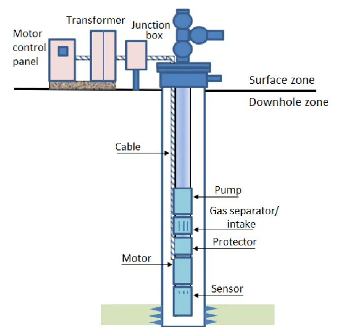
A complete ESP system comprises several integrated components:
Downhole pump: A multistage centrifugal pump (typically 4-20 stages) housed in a pressure-rated sleeve. Each stage adds incremental pressure rise of 100-200 psi, enabling total pressure development of 500-4,000 psi. Stage count is customized to well depth and desired production rate using performance curves.
Submersible electric motor: A three-phase, squirrel-cage induction motor with thermal and pressure-rated insulation. Motors range from 1-2 horsepower (minimal flow applications) to 500+ horsepower for high-rate wells. Operating temperatures near downhole conditions (150-350°F) demand specialized thermal design and cooling provisions.
Intake assembly: Located above the pump, this component screens produced fluid, separates free gas (via internal gas separator), and directs liquid to the pump inlet. Gas separation prevents gas-locking of pump stages—a condition where gas pockets prevent liquid displacement.
Pump cable: A flat or round electrical cable carries power from surface control systems through the wellbore to the downhole motor. Cable insulation withstands high temperatures, mechanical abrasion against tubing, and chemical attack from corrosive produced fluids.
Seal section: Pressure-compensated seals separate the motor’s electrical cavity from produced fluids. These critical components prevent water ingress into motor windings and equalize pressure changes as the well cycles.
Surface equipment: A transformer reduces utility voltage to the three-phase motor supply voltage (380-575V typical). Variable-frequency drives (VFDs) permit shaft speed modulation, enabling production optimization and equipment life extension. Motor soft-starters limit inrush current during startup.
Performance Characteristics and Operational Envelope
ESP performance curves define the relationship between volumetric flow rate (x-axis, 0-100,000+ bbl/day) and total pump head (y-axis, in feet of fluid column). These curves are typically provided for standard motor speed (3,500 rpm at 60 Hz nominal), allowing operators to scale performance across variable-frequency drive settings.
Total head is converted to discharge pressure using the relationship:
P=0.433×ρ×H
Where:
- P = discharge pressure (psi)
- ρ = fluid specific gravity (dimensionless)
- H = total head (feet)
The constant 0.433 converts hydrostatic pressure gradient to psi per foot for freshwater.
Total system head comprises several components:
Static head: The vertical elevation difference between downhole pump location and surface discharge point. A pump set 8,000 feet deep in a vertical well must develop sufficient head merely to lift the produced fluid column this distance.
Dynamic friction losses: Pressure drop across tubing, fittings, separators, and surface piping increases with flow rate. The Fanning equation quantifies friction losses in pipelines for both laminar and turbulent regimes.
Back-pressure: Separator gas pressure, export line pressure, or tank pressure that the ESP must discharge against. Wells connected to common gathering headers share this back-pressure characteristic.
Centrifugal head development: The pump curve defines how much additional head the impeller stages contribute at a given flow rate.
Well productivity (inflow performance relationship, IPR) intersects the total system pressure-flow relationship (tubing performance relationship, TPR). This intersection, found via nodal analysis, establishes the achievable production rate. An undersized ESP results in under-production; an oversized system incurs unnecessary capital and operating costs.
Technological Advantages
ESP systems achieve production rates impossible with alternative artificial lift methods. Properly sized units lift 5,000-50,000 bbl/day from depths exceeding 13,000 feet—capabilities unmatched by rod pumps, gas lift, or progressive cavity alternatives in high-rate scenarios.
Downhole installation eliminates the surface footprint required by rod pump derricks or gas lift facilities. Offshore platforms with limited space or congested facilities benefit significantly from this compact subsurface deployment.
Efficiency ratings of 40-70% (overall system efficiency from electrical input to produced fluid lift) exceed many alternative lift methods, translating to lower operating costs and reduced emissions in the long run.
Versatile capacity adjustment is possible through VFD speed modulation. A single ESP can be tuned to varying production targets without physical equipment changes—a flexibility valuable as reservoirs deplete or field development plans evolve.
Technical Challenges and Failure Modes
Gas locking: Free gas entering the pump intake bypasses centrifugal stages, preventing liquid displacement. Modern intake gas separators address this issue but incur additional cost and complexity.
Sand production: Abrasive sand particles erode impeller vanes and pump bowl erosion-resistant coatings, leading to performance degradation and premature replacement. Wells with significant sand production require protective desanding equipment or alternative lift systems.
High water cut: As wells mature, water production increases, raising the fluid density and requiring greater horsepower for equivalent oil lift. Water cuts exceeding 80-90% challenge motor cooling and thermal stability.
Temperature extremes: High-temperature wells (300°F+) demand specialized insulation, motor cooling, and cable materials, significantly increasing equipment cost.
Scale and paraffin deposition: Mineral scales and hydrocarbon deposits accumulate on pump internals, reducing flow passages and impairing performance. Regular chemical treatment or mechanical cleaning becomes necessary.
Field Applications in Oil and Gas
High-rate well production: Primary application in onshore unconventional plays (Permian Basin, Bakken Formation) and deepwater Gulf of Mexico fields where high flow rates (5,000-30,000+ bbl/day) justify capital investment.
Artificial lift in deep, high-productivity wells: Wells with natural decline or insufficient reservoir pressure deploy ESP systems to maintain economic flow rates during field depletion cycles.
Water disposal wells: Dual-purpose ESP applications pump produced water to disposal wells at high rates, enabling surface water management in areas with limited treatment capacity.
4. Progressive Cavity Pumps (PCP): Viscous Fluid and Heavy Oil Specialists
Operating Principle: Helical Rotor-Stator Design
Progressive cavity pumps represent a unique positive displacement technology optimized for handling viscous fluids, abrasive slurries, and gas-liquid mixtures. The pump operates via helical screw principles—an eccentric rotor (inner element) rotating within a fixed double-helical stator (outer element).
The rotor is typically a single-start helical screw; the stator is a double-start helical cavity. As the rotor rotates, the geometry creates a series of expanding and contracting discrete cavities between the rotor and stator walls.
The pumping cycle consists of progressive stages:
- Suction phase: As rotor rotation expands cavity volumes in the lower region, internal pressure decreases below intake manifold pressure, opening the suction check valve and drawing fluid into the expanding cavities.
- Transit phase: Continued rotation moves the filled cavities upward within the stator. Fluid remains sealed within each cavity, progressively advancing toward the discharge manifold. The cavity volume remains nominally constant, preventing premature pressure rise.
- Discharge phase: As rotor rotation progresses into the upper stator section, cavity volumes decrease due to the converging rotor-stator geometry. Decreasing volume raises internal pressure above system discharge pressure, opening the discharge check valve and expelling sealed fluid into the discharge manifold.
This cavity progression creates smooth, pulsation-free linear flow—typically less than 2% flow ripple, comparable to centrifugal systems.
Pump Geometry and Fluid Handling Capacity
PCP designs are characterized by the cavity count and rotor-stator eccentricity. Common configurations include 2+3, 3+4, 4+5, 5+6, and 6+7 cavity designs (rotor + stator count). Higher cavity counts provide smoother flow but reduce individual cavity volume, limiting maximum pressure capacity.
A critical distinction is the elastomer material selection for stator internal liners. Progressive cavity pumps employ specialized rubber compounds that resist swelling, hardening, and chemical attack from produced fluid exposure. Common stator elastomers include:
- Natural rubber: Lowest cost, suitable for light-to-medium crude, limited viscosity range
- Nitrile (NBR): Better chemical resistance, moderate temperature stability
- EPDM: Superior water and steam tolerance
- Metallic stators: Used in ultra-heavy crude applications where elastomer degradation is problematic
The volumetric displacement per rotor revolution depends on cavity geometry and rotor length. Displacement equations integrate the rotor-stator lobe geometry over the pumping length. Typical displacements range from 0.5 to 5.0 barrels per revolution for industrial PCP configurations.
Flow rate is calculated as:
Q=Vd×N×ηv
Where:
- V_d = displacement per rotor revolution (bbl/rev)
- N = rotational speed (rev/min)
- η_v = volumetric efficiency (typically 75-90%)
Advantages in Viscous Fluid and Heavy Oil Service
Progressive cavity pumps excel in heavy oil and extra-heavy bitumen production—applications where viscosities exceed 1,000 centipoise, rendering centrifugal and ESP systems ineffective. Canadian heavy oil fields (Cold Heavy Oil Production with Sand, CHOPS) and Venezuelan Orinoco Belt operations rely on PCP technology to establish economic production from otherwise immobile reserves.
Pressure rating is consistent across the operating envelope. Unlike centrifugal systems, where head decreases with flow increase, PCP discharge pressure remains nearly constant across turndown ratios from 10:1 to 50:1. This stability permits low-flow production from marginal wells without additional pressure control devices.
High sand tolerance is another decisive advantage. The continuous rotor-stator sliding contact, with low fluid velocities within the pump (typically 2-4 ft/sec) compared to centrifugal impeller surface speeds (100+ ft/sec), dramatically reduces erosion. Wells producing 500-1,500 barrels per day of sand suspension can sustain 12-24 month pump life with properly selected materials.
Gas handling capability exceeds alternative downhole lift systems. Modern PCP designs incorporate dedicated gas-handling geometry that efficiently manages gas-liquid mixtures in wells with gas-to-oil ratios (GOR) up to 40-50%. This advantage makes PCPs attractive in unconventional plays where solution gas drives production.
Volumetric efficiency (typically 75-90%) significantly exceeds alternative positive displacement systems under high-viscosity, high-pressure conditions, reducing power requirements and operating costs.
Limitations and Field Constraints
Stator elastomer degradation remains the primary life-limiting factor. Exposure to certain stimulation fluids (particularly acids containing corrosive ions), extreme temperatures exceeding elastomer rating, or incompatible chemicals causes rapid stator softening, swelling, or hardening. Premature failure necessitates expensive workover interventions.
Paraffin and scale deposition within the pump reduces available cavity volumes, increasing discharge pressure and parasitic power draw. In waxy crude applications, periodic chemical treatment or mechanical pigging becomes necessary.
Maximum pressure capacity is typically 2,000-4,000 psi for standard metallic housing. Unlike reciprocating plunger pumps, scaling PCP designs to extreme pressures (>5,000 psi) requires substantial geometric changes and material upgrades, increasing cost significantly.
Rotational speed limitation comes from elastomer property constraints and hydrodynamic forces. Optimal operating speed ranges from 50-300 rpm for most applications. Higher speeds exceed rotor centrifugal load limits or elastomer stress tolerances.
Rotor-stator sealing depends on precise machining and close running clearances (often <1 mm). Debris or particulates jamming these tight tolerances cause catastrophic stator wear or rotor seizure.
Field Applications in Oil and Gas
Extra-heavy crude artificial lift: Primary application in Western Canada (Athabasca, Cold Lake, Cretaceous) where bitumen viscosity reaches 5,000-10,000 cP. PCP systems equipped with large-diameter downhole motors maintain production from CHOPS wells despite extremely high fluid viscosity.
High-viscosity oil wells: Medium crude (15-22 API) and heavy crude (10-15 API) wells worldwide employ PCP technology. Vertical, deviated, and horizontal well configurations all utilize PCPs effectively.
High-sand-production wells: Coal seam gas dewatering, solution gas wells with sand cut, and unconventional reservoirs (shale, tight sand) producing significant particulate loads favor PCP deployment to maximize interval run life.
Multiphase and gas-loaded wells: Wells with high gas-to-oil ratios (>2,000 scf/bbl) can be produced via PCP with proper gas-handling stator geometry selection, avoiding the deliquification challenges of alternative systems.
5. Gear Pumps: Positive Displacement for Medium-Viscosity Transfer
Pump Design and Operating Mechanics
Gear pumps represent another positive displacement category utilizing meshing gears to mechanically displace fluid. Two principal gear pump designs serve oil and gas applications: external gear pumps and internal gear (gerotor) pumps.
External Gear Pump Architecture:
Two spur gears of equal size mesh within a precisely machined pump casing. One gear connects to an external motor (driving gear); the other rotates freely (driven gear). As gears rotate, the meshing action creates expanding cavities on the inlet side and contracting cavities on the discharge side.
Operating mechanism:
- Inlet region: Tooth-mesh separation expands the cavity volume, creating pressure drop below atmospheric. Atmospheric pressure on the fluid surface pushes fluid from the inlet manifold into the expanding tooth spaces.
- Transit: Fluid occupies discrete pockets between adjacent teeth and the casing wall, progressing around the gear periphery as the gears rotate.
- Outlet region: Tooth-mesh engagement compresses cavity volumes, raising internal pressure above system discharge pressure. The discharge check valve opens, expelling trapped fluid into the discharge manifold. The teeth re-engage, sealing against backward leakage.
This intermittent displacement creates significant pulsation (5-10% flow ripple), requiring discharge pulsation dampers in many applications.
Internal Gear (Gerotor) Configuration:
The gerotor design eliminates the crescent-shaped divider used in traditional internal gear pumps. Instead, an eccentric internal rotor (N teeth) rotates within a fixed external rotor (N+1 teeth). The off-center mounting creates continuously variable cavity volumes.
As the internal rotor rotates:
- Expanding cavities (inlet side) draw fluid as volume increases
- Contracting cavities (discharge side) force fluid as volumes decrease due to lobe convergence
Gerotor geometry produces exceptionally smooth flow (< 2% pulsation), approaching centrifugal performance smoothness. The design also tolerates higher speed operation (up to 3,600 rpm for premium designs) compared to external gear pumps (typically limited to 1,800 rpm).
Technical Characteristics and Performance
Flow displacement for gear pumps is defined by the gear tooth volume per revolution. External gear pump displacement increases with pitch diameter and gear width, calculated via gear geometry parameters. Practical displacement ranges from 0.1 to 10+ cubic inches per revolution.
Pressure capacity is determined by:
- Material strength of gear teeth and casing
- Bearing adequacy to handle thrust and radial loads
- Seal design to maintain internal pressurization
External gear pumps typically operate to 1,500-3,000 psi; some specialized designs reach 5,000 psi. Gerotor pumps are generally limited to 500-1,500 psi due to geometric constraints on cavity pressure distribution.
Volumetric efficiency (ratio of actual flow to theoretical displacement flow) typically ranges 85-95% for well-maintained gear pumps. Primary leakage sources include:
- Tooth clearance to casing
- Bearing leak-past
- Valve seat leakage
- Internal case drain flow (if external drain required)
Advantages in Oil and Gas Service
Versatile viscosity range: Gear pumps handle fluids from light oils (ISO 32) through heavy crude (ISO 1000+) without performance degradation. Unlike centrifugal pumps, which fail with increasing viscosity, gear pumps maintain near-constant volumetric efficiency across viscosity ranges.
Robust to contamination: The simpler design with fewer internal surfaces tolerates moderate particulate content better than centrifugal impellers. Sand or scale particles may increase internal leakage but rarely cause catastrophic failure.
Compact design: Gear pumps achieve high displacement in minimal envelope, advantageous in space-constrained applications or subsurface deployments.
Constant displacement: Like other positive displacement pumps, gear designs deliver fixed flow per revolution regardless of discharge pressure, enabling precision metering applications.
Limitations and Design Constraints
Pulsation: External gear pump flow ripple demands discharge accumulators to protect instrumentation and reduce pipeline fatigue in production systems.
Noise generation: The intermittent tooth engagement produces characteristic high-frequency noise. Industrial applications require soundproof enclosures or equipment isolation to meet occupational noise exposure limits.
Speed limitations: Gear mesh-line forces increase with rotational speed (force proportional to rpm²). Most external gear designs are limited to 1,800-2,400 rpm to avoid excessive bearing loads and tooth contact stresses. Gerotor designs tolerate higher speeds (2,400-3,600 rpm) but at increased internal stress.
Maintenance intensity: Gear tooth wear, bearing degradation, and seal leakage require regular monitoring. Maintenance intervals are shorter than equivalently sized centrifugal or reciprocating systems.
Case drain requirement: Some gear pump configurations require external case drain lines returning internal leakage to the inlet tank. This additional plumbing increases system complexity and cost.
Field Applications in Oil and Gas
Fuel oil and lube oil circulation: Heating systems, purification loops, and storage tank transfer operations employ gear pumps to move low-viscosity petroleum products at moderate pressures (100-500 psi).
Glycol and amine solution circulation: Gas dehydration units and acid-gas treating systems circulate regeneration fluids through contactor columns at controlled rates. Gear pumps provide the precise, pulsation-free flow required by these processes.
Transferring high-viscosity process fluids: Bitumen heating, dilution systems, and heavy oil pre-heating operations employ gear pumps to circulate viscous fluids efficiently.
Chemical solution transfer: Pump corrosion inhibitors, scale inhibitors, and other process chemicals from bulk storage to injection skids.
6. Diaphragm and Metering Pumps: Precision Chemical Injection
Diaphragm Pump Technology and Operation
Diaphragm pumps represent a specialized positive displacement technology designed for precise, low-volume metering of corrosive or chemically aggressive fluids. These pumps employ a flexing diaphragm actuated by mechanical or hydraulic linkages to create controlled suction and discharge strokes.
Mechanical Diaphragm Design:
A rigid diaphragm (typically PTFE, elastomer, or composite) is mechanically coupled to a reciprocating piston. As an external crankshaft rotates:
- Suction stroke: The piston retracts, pulling the diaphragm downward. The expanding chamber draws fluid through the suction check valve.
- Discharge stroke: The piston advances, pushing the diaphragm upward. The compressed fluid pressure rises above system discharge pressure, opening the discharge check valve and expelling metered volume.
Mechanical diaphragm pumps generate highly precise displacement—typical repeatability is ±1-2% across many cycles.
Hydraulic Diaphragm Variant:
A piston pump creates controlled hydraulic pressure in a secondary cavity, which flexes the diaphragm. This hydraulic actuation decouples the diaphragm from mechanical stresses, extending diaphragm life in corrosive or abrasive service. Hydraulic actuation also enables electronic proportional control, adjusting displacement by varying hydraulic pressure across a wide range (often 10:1 turndown or greater).
Double-Diaphragm Safety Architecture
Critical chemical injection applications employ double-diaphragm designs—two diaphragms in series with a leak detection chamber between them. If either diaphragm ruptures:
- The outer (primary) diaphragm maintains pressure containment temporarily
- The inner (secondary) diaphragm provides redundancy
- Fluid escaping the rupture site enters the detection chamber, triggering automatic alarm and shutdown
This design is mandatory for volatile chemicals (methanol, glycol) that pose environmental or safety hazards if released uncontrolled.
Performance Characteristics
Metering pump displacement is typically modest—0.1 to 5 gallons per hour in standard industrial designs—enabling precise chemical dosing at low flow rates. Discharge pressure rating ranges from 500 psi (simple diaphragm designs) to 15,000 psi+ (advanced metallic diaphragm constructions).
Accuracy in metering applications is critical. Advanced control systems with electronic proportional valves maintain ±1% accuracy across 10:1 or greater turndown ratios. This precision ensures chemical inhibitor concentrations remain within optimal windows (typically 50-500 ppm depending on inhibitor type).
Volumetric efficiency is high for metering duty—typically 90-98%, limited only by minor valve seat leakage and diaphragm edge weep.
Advantages in Oil and Gas Chemical Service
Chemical compatibility: Diaphragm and metering pump internals are constructed from PTFE, stainless steel, or specialized elastomers that resist attack from corrosive inhibitors, demulsifiers, and biocides. Conversely, positive displacement piston or gear pumps with ferrous internals corrode rapidly in chemical service.
Precise dosing: Electronic controls enable automatic adjustment of metering rates based on production volume, well pressure, or other process parameters. PLC integration allows remote optimization across multiple wells or facilities.
Pulsation-free discharge: Modern metering pump designs produce extremely smooth flow, eliminating the pulsation damper requirements of reciprocating alternatives. This simplicity reduces system cost and piping complexity.
Low power consumption: Metering duties consume minimal horsepower (0.5-2 HP typical), enabling battery backup or solar-powered systems in remote locations.
Self-priming: Metering pumps prime themselves without external priming lines or check valves, simplifying installation and reducing startup procedures.
Limitations and Field Constraints
Low flow capacity: Metering pumps are fundamentally low-flow devices. Total system flows rarely exceed 50 gallons per hour. High-volume chemical circulation (e.g., bulk glycol regeneration) requires alternative pump types.
Diaphragm life sensitivity: Diaphragm degradation is accelerated by temperature extremes, aggressive chemicals, or excessive cycling pressure. Expected diaphragm life ranges from 6 months to 2 years depending on application severity.
Valve sensitivity: Check valves in metering pumps are particularly susceptible to debris jamming or coating from viscous fluids. Inlet strainers (typically 100 mesh minimum) are mandatory.
Turndown ratio limits: While electronic proportional drives enable broad turndown, pump efficiency and accuracy may degrade at extremely low stroke rates. Practical operating windows are typically 5:1 to 20:1 turndown ratios.
Field Applications in Oil and Gas
Corrosion inhibitor injection: Upstream wells and export pipelines inject filming amine or oleophobic corrosion inhibitors at controlled concentrations (typically 100-300 ppm). Metering pumps dose these inhibitors from centralized tanks into main production headers, protecting ferrous internals from corrosive formation waters and CO₂/H₂S.
Scale inhibitor treatment: Phosphonate and polymeric scale inhibitors are metered into wells or production systems to prevent mineral deposition (CaCO₃, BaSO₄) that would reduce flow capacity or plug perforations. Squeeze treatments inject large inhibitor slugs at intervals (monthly to quarterly); continuous low-rate metering provides ongoing protection.
Demulsifier dosing: Crude oil-water emulsions are stabilized by naturally occurring surfactants and fine solids. Demulsifier chemicals destabilize these emulsions, promoting rapid oil-water separation. Low-volume metering (typically 50-200 ppm) into crude stabilization facilities improves separation efficiency, reducing treatment vessel residence time and increasing throughput.
Methanol and glycol injection: Cold-climate wells and subsea pipelines are prone to hydrate blockage if water condenses in the hydrocarbon stream. Thermodynamic inhibitors (methanol, ethylene glycol) depress the hydrate formation temperature. Metering pumps inject these inhibitors continuously during production to prevent blockages. Double-diaphragm designs are mandatory due to methanol volatility and toxicity.
H₂S scavenger injection: Wells and associated gas streams containing hydrogen sulfide employ aldehyde-based or triazine scavengers to chemically bind and neutralize H₂S, reducing corrosion and improving safety. Metering pumps inject scavengers continuously or intermittently to maintain downhole concentrations.
Biocide injection: Water-injection systems and low-producing wells are susceptible to microbial (bacteria, sulfate-reducing bacteria) growth, which accelerates corrosion and clogs perforations. Periodic metering injection of biocides (glutaraldehyde, isothiazole) controls microbial populations, extending well life and reducing injection costs.
Pump Selection and Optimization: Key Decision Criteria
Reservoir and Well Condition Assessment
Successful pump selection begins with comprehensive well characterization. Critical parameters include:
Well depth and geometry: Vertical wells, deviated boreholes, and horizontal wells demand different lift systems. Horizontal wells (>45°) may not tolerate rod pump installations; ESP or PCP systems are preferred.
Reservoir pressure and productivity: Calculate the inflow performance relationship (IPR) via pressure transient analysis. Wells with high productivity index (high natural flow capacity) may not require artificial lift. Wells with depleted reservoirs or low productivity benefit from ESP or PCP systems that can handle extreme pressure conditions.
Fluid properties:
- Viscosity: Light crude (>30°API) accommodates centrifugal, ESP, or reciprocating systems. Heavy crude (10-20°API) or bitumen (<10°API) requires PCP technology.
- Gas content: High gas-to-oil ratios (>1,000 scf/bbl) challenge most downhole pumps; plunger lift or gas lift systems are preferred. Moderate GOR (<500 scf/bbl) is manageable by modern ESP or PCP designs.
- Water cut: High water production (>70%) increases fluid density and pumping power demands. Corrosion inhibition becomes critical. Alternative lift methods should be evaluated.
- Sand production: Significant sand cut (>100 ppm) demands PCP or jet pump systems; ESP and rod pumps are less tolerant.
- Temperature: Extreme wellbore temperatures (>250°F) limit elastomer and electronic component options, driving cost and technology selection.
Production rate objectives: Target production rate (barrels per day) filters the viable pump technology set. Table 1 summarizes typical production rate ranges for major artificial lift methods.
Nodal Analysis for Lift System Optimization
Nodal analysis is a systematic pressure-flow calculation method that predicts achievable production rates given well and lift system characteristics. The technique divides the well system at a selected node (analysis point) into upstream (inflow) and downstream (outflow) sections.
Inflow Performance Relationship (IPR): Describes how much fluid the reservoir can deliver at various wellbore pressures. IPR is obtained from well-test data, type-curve matching, or empirical correlations. For constant bottomhole flowing pressure, flow rate relates to pressure drawdown:
Q=J(Pr−Pwf)
Where:
- Q = flow rate (BOPD)
- J = productivity index (BOPD/psi)
- P_r = reservoir pressure (psia)
- P_{wf} = wellbore flowing pressure at the node (psia)
Tubing Performance Relationship (TPR): Describes the pressure drop required to deliver a given flow rate through the well completion, tubing, and surface facilities to a reference pressure (typically separator or tank pressure). TPR combines:
- Hydrostatic pressure: ρgh (function of fluid density and depth)
- Friction pressure drop: calculated via Darcy-Weisbach or Fanning equations for turbulent/laminar regimes
- Kinetic energy changes: typically negligible for liquid flow
Lift System Curve: Graphically represents the pressure boost provided by the pump across a range of flow rates. For ESP systems, multistage configurations shift the TPR downward, allowing higher flow intersection with IPR. Proper pump selection aims to achieve the economically optimal intersection of IPR and modified TPR curves.
Comparative Advantages and Trade-offs
The following table summarizes key selection characteristics across major pump types:
| Pump Type | Production Rate Range (BOPD) | Max Depth (ft) | Viscosity Limit | Sand Tolerance | Gas Handling | CAPEX | OPEX |
|---|---|---|---|---|---|---|---|
| Centrifugal | 500-100,000+ | Unlimited (surface) | <100 cP | Poor | Poor | Low | Low |
| Reciprocating | 50-5,000 | Unlimited (surface) | Unlimited | Good | Poor | Medium | High |
| ESP | 1,000-50,000 | 13,000 | 500 cP | Moderate | Poor (w/ gas sep.) | Medium-High | Medium |
| PCP | 100-10,000 | 10,000 | Unlimited | Excellent | Good | Medium | Medium-High |
| Gear Pump | 500-5,000 | Unlimited (surface) | <1,000 cP | Moderate | Poor | Low | Medium |
| Diaphragm | <50 | Unlimited (surface) | Unlimited | Fair | Poor | Low | Low |
| Rod Pump | 50-3,000 | 12,000 | 500 cP | Moderate | Poor | Low | Low |
| Plunger Lift | 50-2,000 (intermittent) | 10,000 | – | Good | Excellent | Low | Low |
Economic evaluation must weigh initial capital costs (equipment, installation, testing) against projected operating costs (power, maintenance, interventions) over the well’s expected economic life. A lower-cost surface pump may be economically inferior if servicing requires expensive wireline interventions or production shutdowns.
Conclusion: Integrated Systems and Future Outlook
Modern oil and gas operations increasingly employ hybrid artificial lift strategies, combining multiple technologies to optimize production across diverse well types. A typical field portfolio might include:
- Centrifugal pumps for low-viscosity crude transportation and water injection
- ESP systems for high-rate, deep conventional wells
- PCP technology for heavy oil and high-sand-production unconventional wells
- Gas lift and plunger lift for high-GOR, low-rate marginal wells
- Reciprocating and metering pumps for precise chemical injection and drilling applications
Digital transformation is revolutionizing pump optimization. Real-time downhole monitoring via fiber-optic sensors and wireless telemetry provides continuous pressure, temperature, and flow data. Machine learning algorithms analyze this data to predict component wear, optimize pump speeds via VFDs, and schedule maintenance proactively. Predictive models reduce unplanned downtime, extend equipment life, and maximize production.
Sustainability pressures are driving research into higher-efficiency pump designs and electric power integration. Offshore and remote wells are transitioning from diesel-powered surface systems to subsea electrical grids and battery-powered hybrid configurations, reducing emissions and operating costs.
Unconventional resource development (shale, tight sands, heavy oil) continues to expand the operational envelope for specialized pump types. Enhanced understanding of multiphase flow, non-Newtonian fluid behavior, and erosion resistance is enabling next-generation pump designs for the most challenging production scenarios.
The petroleum engineer’s role in pump selection and optimization remains critical. Integrating reservoir engineering, production operations, process design, and equipment expertise ensures that selected systems deliver maximum productivity, lowest lifecycle cost, and safe, reliable operation across the diverse conditions encountered in modern oil and gas fields.