
 Edu_Admin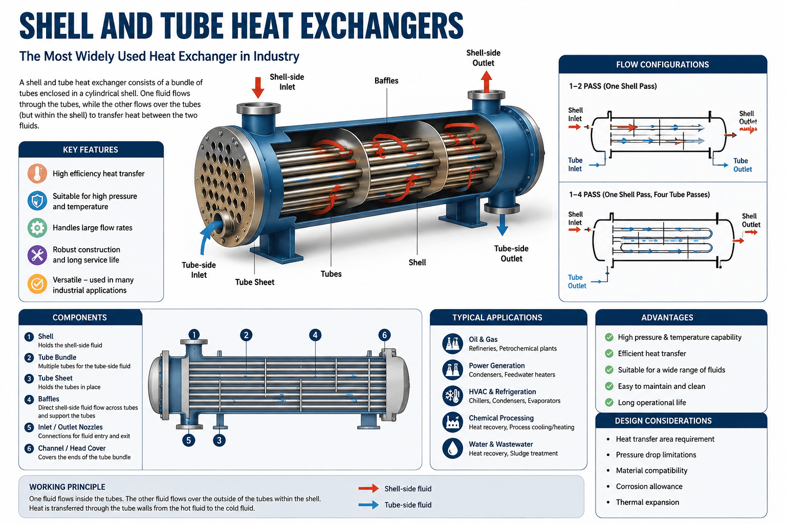
Introduction
The shell and tube heat exchanger stands as the undisputed workhorse of industrial processes. Walk into any oil refinery, chemical plant, power station, or fertiliser facility, and you will find these cylindrical pressure vessels hard at work, transferring thermal energy between fluids without allowing them to mix.
These devices are everywhere. They cool engines, heat buildings, condense steam, and enable countless chemical reactions. Their reliability and efficiency make them indispensable across industries including oil and gas, chemical processing, power generation, food processing, pharmaceuticals, and HVAC systems.
Yet despite their ubiquity, the mechanical aspects of shell and tube heat exchangers remain poorly understood by many engineers. The terminology can be confusing. The design standards appear complex. The components seem numerous and interconnected.
This guide changes that. It provides a clear, practical introduction to the mechanical aspects of shell and tube heat exchangers. No unnecessary jargon. No overwhelming detail. Just the fundamental knowledge every mechanical engineer needs.
What Is a Shell and Tube Heat Exchanger?
A shell and tube heat exchanger is a pressure vessel that consists of a cylindrical shell containing a bundle of tubes. One fluid flows through the tubes while another fluid flows over the tubes through the shell, enabling heat transfer between the two fluids.
The name derives from its two primary components: the shell (the outer cylindrical vessel) and the tubes (the inner bundle that carries one of the fluids). These exchangers are among the most effective means of heat exchange and are suited for higher-pressure applications.
Why Shell and Tube Heat Exchangers Dominate Industry
Several factors contribute to the widespread adoption of shell and tube heat exchangers:
- High Pressure Capability: They can handle extreme pressures and temperatures, making them suitable for demanding industrial applications
- Long Service Life: These units are known for their durability and extended operational life
- Design Flexibility: They can be configured in numerous ways to suit specific process requirements
- Scalability: Designs can be scaled from small laboratory units to massive industrial installations
- Proven Reliability: Decades of industrial use have established their dependability
Key Components of Shell and Tube Heat Exchangers
Understanding the mechanical components is essential for any engineer working with these devices. The main elements include:
The Shell
The shell is the outer cylindrical vessel that contains the tube bundle and the shell-side fluid. It is a pressure vessel designed to withstand the operating pressures and temperatures of the process. Shells can vary in diameter and length depending on the heat transfer requirements.
The Tube Bundle
The tube bundle consists of multiple tubes arranged in a specific pattern. One fluid flows through these tubes, while the other flows over them. The tubes are typically circular, although elliptical, rectangular, or twisted tubes are also used in some applications.
Tubesheets
Tubesheets are thick plates at each end of the tube bundle. The tubes are expanded or welded into these plates, creating a seal between the tube-side and shell-side fluids.
Baffles
Baffles are plates placed inside the shell to direct the shell-side fluid flow across the tubes. They serve two purposes:
- They increase heat transfer by creating turbulence
- They support the tubes, preventing sagging and vibration
Channels and Heads
The channels and heads are the end closures of the exchanger. They distribute fluid to the tubes and collect it on exit. Different designs exist for different applications.
Tie Rods and Spacers
These components hold the baffle assembly together and maintain proper spacing between baffles.
Types of Shell and Tube Heat Exchangers
Shell and tube heat exchangers are classified using the TEMA (Tubular Exchanger Manufacturers Association) three-digit code system, which specifies the types of front-end head, shell, and rear-end head. The most common types include:
Fixed Tubesheet Exchanger (TEMA AEM)
This is the simplest and most economical type. The tubesheet is welded directly to the shell, making the tube bundle non-removable. It provides maximum heat transfer area for a given shell and tube diameter and allows for single and multiple tube passes.
Advantages:
- Lower cost than removable bundle designs
- No leakage path between shell and tubes
- Simple construction
Disadvantages:
- Tube bundle cannot be removed for cleaning
- Thermal expansion must be accommodated
U-Tube Exchanger (TEMA BEU, AEU)
In this design, the tubes are bent into a U-shape. Both ends of each tube are fixed in the same tubesheet.
Advantages:
- Tube bundle can be removed for cleaning
- Accommodates thermal expansion naturally
- Less costly than removable bundle designs
Disadvantages:
- Cannot use straight tubes
- Cleaning the inside of U-bends is difficult
Floating Head Exchanger
This design allows the tube bundle to expand and contract independently of the shell. The rear tubesheet is not fixed to the shell, allowing it to “float.”
Advantages:
- Accommodates significant thermal expansion
- Tube bundle is removable
- Suitable for high-temperature differentials
Disadvantages:
- More complex and expensive
- Potential for leakage at the floating head seal
Design Standards and Codes
The mechanical design of shell and tube heat exchangers is governed by several international standards and codes.
TEMA Standards
TEMA provides the most widely recognised standards for the mechanical design of shell and tube heat exchangers. The TEMA standards cover:
- Design and construction requirements
- Materials specifications
- Tolerances and clearances
- Testing and inspection procedures
TEMA three-digit codes specify the types of front-end, shell, and rear-end configurations.
ASME Code
The ASME Boiler and Pressure Vessel Code, particularly Section VIII, provides the regulatory framework for pressure vessel design. This code covers:
- Pressure containment requirements
- Material selection criteria
- Fabrication and welding standards
- Non-destructive testing requirements
API Standards
API 660 provides additional requirements for shell and tube heat exchangers used in petroleum and chemical industries.
Mechanical Design Considerations
Several critical factors influence the mechanical design of shell and tube heat exchangers.
Material Selection
Material choice is crucial for exchanger performance and longevity. Factors to consider include:
- Operating temperature and pressure
- Corrosion resistance
- Physical properties
- Fabrication methods
- Cost and availability
Pressure Containment
The exchanger must safely contain the operating pressures. This requires:
- Proper shell and tubesheet thickness calculations
- Bolted flange joint design
- Nozzle reinforcement
- Support saddle design
Thermal Expansion Management
Temperature differences between the shell and tubes create thermal expansion stresses. These must be accommodated through:
- Expansion joints in the shell
- Floating head designs
- U-tube configurations
- Proper support design
Flow-Induced Vibration
Shell-side fluid flowing across the tube bundle can cause vibration. This can lead to:
- Tube wear and fretting
- Fatigue failure at tubesheet connections
- Noise generation
Proper baffle spacing and tube support design minimise these risks.
Quality Control and Inspection
Quality control is essential throughout the manufacturing process. This includes:
- Non-destructive testing of welds
- Hydrostatic testing
- Dimensional inspection
- Material certification verification
Common Failure Mechanisms
Shell and tube heat exchangers can experience various failure modes that engineers must understand and prevent.
Tube-to-Tubesheet Joint Failure
This is one of the most common failure locations. Causes include:
- Loss of initial tightness
- Poor welding quality
- Thermal cycling stress
- Corrosion at the joint
Tube Corrosion
Tubes can corrode due to:
- Fluid chemistry incompatibility
- Erosion from high-velocity fluids
- Galvanic corrosion between dissimilar materials
- Stress corrosion cracking
Flow-Induced Vibration Damage
Vibration can cause:
- Tube wear at baffle supports
- Fatigue failure
- Fretting damage
Thermal Fatigue
Repeated thermal cycling can cause:
- Cracking at stress concentration points
- Fatigue failure of tubesheet connections
- Gasket failure at flanges
The Importance of Proper Training
Shell and tube heat exchangers are complex pieces of equipment. Their design, operation, and maintenance require specialised knowledge that is rarely covered adequately in university curricula.
This is where targeted professional training becomes invaluable. The right course can:
- Bridge the gap between academic theory and industrial practice
- Provide practical knowledge of components and their functions
- Explain relevant codes and standards
- Develop the skills needed for equipment selection and specification
- Build confidence for fresh graduates entering the industry
Mastering Mechanical Aspects: Your Next Step
Learning the mechanical aspects of shell and tube heat exchangers presents a choice. You can struggle through dense technical manuals and fragmentary online resources. Or you can take a structured course designed specifically for students and new professionals in the industry.
The Mechanical Aspects of Shell and Tube Heat Exchangers course provides exactly this structured approach. The course includes:
- 2.5 hours of on-demand video content in an easy-to-understand style
- Coverage of different types of shell and tube heat exchangers
- Detailed explanation of main components, with pictures and sketches to simplify construction
- Advantages and disadvantages of each exchanger type
- How each type works in practice
- Clarity on how parts are assembled
- Connection to relevant codes and standards
- Multiple choice quizzes at the end of each module for better understanding
- 15 downloadable resources
- Certificate of completion
The course is ideal for engineers, designers, operators, technicians, or anyone interested in shell and tube heat exchangers, as well as fresh graduates entering the industry. No prior knowledge is required.
Enrol in Mechanical Aspects of Shell and Tube Heat Exchangers Now
Recommended Related Courses
To build a comprehensive understanding of heat exchangers and mechanical equipment, consider these additional courses:
Thermodynamics for Mechanical Engineering – Build foundational knowledge in thermodynamics for understanding heat transfer processes.
Mechanical Engineering-Machine Designing-1 – Develop machine design skills applicable to heat exchanger components.
Mechanical concept design : Stress simulation in Fusion 360 – Learn stress analysis techniques for verifying heat exchanger designs.
Pressure Vessel Fabrication – Mechanical Engineering, Oil & Gas – Understand fabrication methods relevant to heat exchanger manufacturing.
Basics of Mechanical Design Engineering (2022) – Build fundamental mechanical design skills.
FEA & CFD with ANSYS Mechanical & ANSYS Fluent – For Beginner – Learn simulation techniques for heat exchanger analysis.
Final Thoughts
Shell and tube heat exchangers are fundamental to modern industry. Their mechanical design, construction, and operation require specialised knowledge that every mechanical engineer working in process industries should possess.
Understanding the components, types, design standards, and failure mechanisms of these devices is essential for effective equipment specification, maintenance, and troubleshooting.
Start building your expertise today with the right training and take the next step in your professional development.
Enrol in Mechanical Aspects of Shell and Tube Heat Exchangers
About the Author