

 Edu_Admin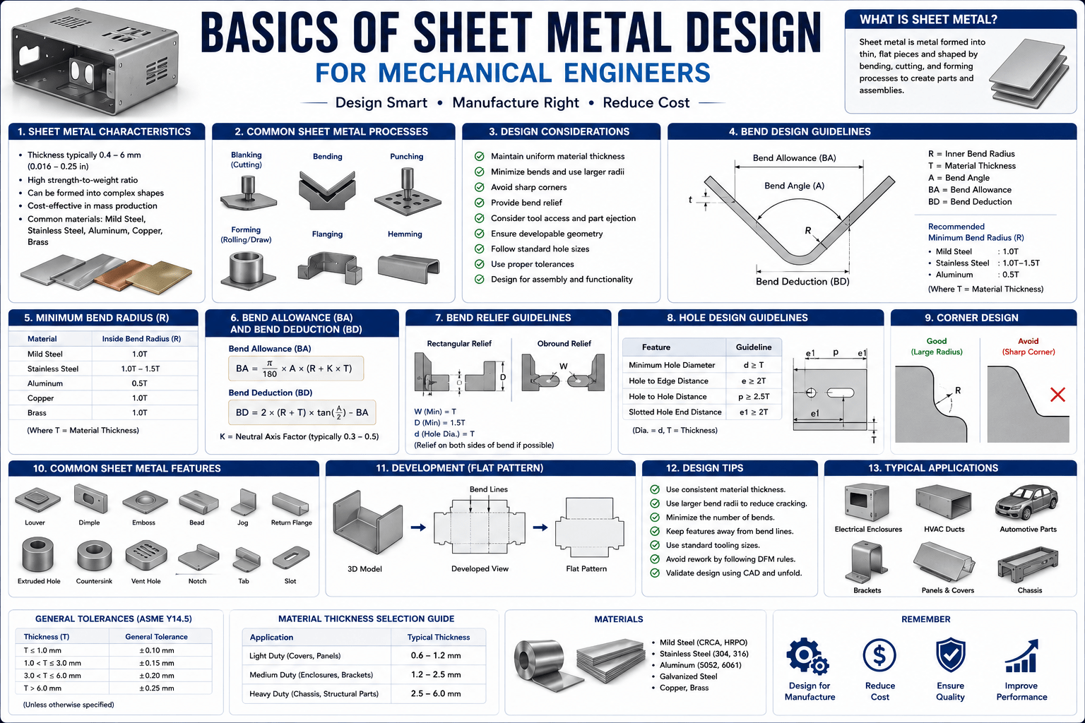
Introduction
Sheet metal is everywhere. Look around any industrial environment, and you will see its presence—enclosures protecting sensitive electronics, brackets supporting heavy equipment, panels forming the exterior of machinery, chassis providing structural integrity to products. Sheet metal design is one of the most versatile and essential skills in mechanical engineering, finding applications across virtually every industry where physical products are manufactured.
Yet for many mechanical engineers and designers, sheet metal design remains unfamiliar territory. The terminology is specialised. The processes are numerous. The design guidelines are exacting. The gap between creating a 3D model and producing a manufacturable part can seem vast.
The truth is that sheet metal design is remarkably logical when understood correctly. It is a discipline governed by the physical behaviour of materials under stress, the capabilities of manufacturing equipment, and the economics of production. Once you understand the principles at play, designing effective sheet metal parts becomes a systematic process rather than an exercise in guesswork.
This guide provides a comprehensive introduction to the basics of sheet metal design for mechanical engineers. It covers what sheet metal is, why it matters, the key manufacturing processes, material properties, bending calculations, design guidelines, and how you can build expertise in this essential engineering discipline.
What Is Sheet Metal Design?
Sheet metal design is the process of creating components and structures from thin metal sheets, typically ranging from 0.5 mm to 6 mm in thickness. The design process involves determining the part geometry, selecting appropriate materials, specifying manufacturing processes, and creating detailed documentation for production.
Sheet metal forming is a manufacturing process that uses various techniques to shape thin metal sheets into desired parts. The main challenge of sheet metal design is to choose the right process and the right order for each step. The process and order depend on factors such as the material properties, the thickness, and the available machines.
Why Sheet Metal Matters
Sheet metal is one of the most widely used materials in product manufacturing due to its unique combination of properties:
- Versatility: Sheet metal can be formed into virtually any shape
- Strength-to-Weight Ratio: Sheet metal structures are strong yet lightweight
- Cost-Effectiveness: Sheet metal fabrication is economical for high-volume production
- Durability: Sheet metal components are robust and long-lasting
- Recyclability: Sheet metal is fully recyclable, supporting sustainability initiatives
Sheet Metal Manufacturing Processes
Understanding the manufacturing processes available is essential for effective sheet metal design. The choice of process affects the part geometry, tolerances, cost, and lead time.
Cutting Processes
Cutting is the first step in sheet metal fabrication, separating the raw material into the required shape.
Laser Cutting: Uses a high-power laser beam to cut through metal with exceptional precision. Ideal for complex shapes and tight tolerances.
Plasma Cutting: Uses an ionised gas to cut through thicker materials. Suitable for heavy-gauge sheet metal.
Water Jet Cutting: Uses a high-pressure stream of water mixed with abrasive particles. Produces no heat-affected zone, preserving material properties.
Shearing: A mechanical process that cuts straight lines using a shear blade. Economical for simple shapes.
Forming Processes
Forming processes shape the sheet metal without removing material. Sheet metal forming processes, such as bending, deep drawing, and stamping, involve relatively small thickness changes and shape the workpiece into a thin-walled shell.
Bending: The most common sheet metal forming process. The metal is deformed along a straight axis, creating a V-shape, U-shape, or other profile.
Deep Drawing: A process in which a flat sheet is formed into a three-dimensional shape, such as a cup or cylinder, using a punch and die.
Stamping: A high-speed process that uses a press and die to cut, form, or emboss sheet metal.
Rolling: Passes the sheet metal through rollers to create curved or cylindrical shapes.
Hydroforming: Uses high-pressure fluid to form the sheet metal against a die.
Stretch Forming: Stretches the sheet metal over a form to create complex curved shapes.
Joining Processes
Joining processes are used to assemble multiple sheet metal components into finished products.
Welding: Fuses metal parts together using heat. Common methods include MIG, TIG, and spot welding.
Riveting: Uses mechanical fasteners to join parts. Suitable for applications where welding is impractical.
Fastening: Uses screws, bolts, or other mechanical fasteners.
Adhesive Bonding: Uses structural adhesives to join parts. Provides a clean appearance and distributes stress evenly.
Material Properties for Sheet Metal Design
Selecting the right material is one of the most critical decisions in sheet metal design. Material choice directly determines strength, weight, corrosion resistance, cost, and manufacturability.
Common Sheet Metal Materials
Steel: The most commonly used sheet metal material. Offers excellent strength, durability, and cost-effectiveness.
- Mild Steel: Low carbon content, easy to form and weld
- High-Strength Low-Alloy (HSLA) Steel: Higher strength for structural applications
- Stainless Steel: Excellent corrosion resistance, used in food processing, medical, and marine applications
Aluminium: Offers an excellent strength-to-weight ratio and resists corrosion. Ideal for creating large, lightweight structures and panels.
Copper and Brass: Offer excellent electrical and thermal conductivity. Used in electrical components and decorative applications.
Galvanised Steel: Steel coated with zinc for corrosion protection. Commonly used in outdoor and automotive applications.
Key Material Properties for Designers
Understanding material properties is essential for effective sheet metal design. Material properties affect the part quality and design considerations.
Strength: The ability of the material to withstand applied loads without failure.
Formability: The ability of the material to undergo shape change without failure by necking or tearing. Choose a suitable material that has good formability, meaning it can bend, stretch, or shear without cracking or breaking.
Hardness: Resistance to indentation and wear. Harder materials are more wear-resistant but more difficult to form.
Toughness: The ability to absorb energy without fracturing. Important for impact-resistant applications.
Elongation: Determines the capability of the sheet metal to stretch without necking and failure.
Corrosion Resistance: The ability to resist chemical degradation in the operating environment.
Anisotropy: The variation of material properties with direction. Important for forming processes because sheet metal properties can differ along rolling and transverse directions.
The Science of Bending
Bending is the most fundamental operation in sheet metal fabrication. Understanding the underlying principles is essential for designing parts that can be manufactured successfully.
What Happens During Bending?
When sheet metal is bent, the material undergoes both stretching and compression. The material on the outside of the bend stretches, while the material on the inside compresses.
The Neutral Axis: An imaginary line within the material that neither stretches nor compresses during bending. The location of the neutral axis is critical for calculating bend allowance.
Tension and Compression: The outside of the bend experiences tensile stress, while the inside experiences compressive stress. If the bend radius is too small relative to the material thickness, the outside surface can crack.
Key Bending Parameters
Bend Radius: The inside radius of the bend. As a general guideline, the inside bend radius should be at least equal to the sheet thickness. Preferably, the inside bend radius should be 2 times sheet thickness.
Bend Allowance: The length of the neutral axis through the bend. Used to calculate the flat blank length required to achieve the final bent part.
K-Factor: The ratio of the neutral axis location to the material thickness. Essential for accurate bend allowance calculations.
Bend Deduction: The amount subtracted from the sum of the flange lengths to account for material stretching during bending.
Spring-Back
Spring-back is the elastic recovery of the material after bending. When the bending force is removed, the material partially returns to its original shape.
Causes: Spring-back occurs because the material experiences elastic deformation in addition to plastic deformation during bending.
Solutions:
- Over-bending: Bend the material slightly past the desired angle to compensate for spring-back
- Coining: Apply sufficient force to eliminate spring-back entirely
- Material selection: Materials with higher yield strength exhibit more spring-back
Wrinkling
Wrinkling is a common defect in sheet metal forming, particularly in deep drawing operations. It occurs when compressive stresses cause the material to buckle.
Causes:
- Insufficient blank holder force
- Inadequate material thickness
- Improper tooling design
Solutions:
- Increase blank holder pressure
- Use draw beads to control material flow
- Select materials with better formability
Design for Manufacturability (DFM) Guidelines
Design for Manufacturability is the practice of designing parts that are easy and economical to manufacture. DFM guidelines help companies avoid rejections and rework due to engineering errors, leading to higher cost of quality and delays in delivery to the customer.
General DFM Principles
Simplify Designs: Reduce part complexity and part count. DFMA focuses on simplifying designs and reducing the parts count. It suggests using standardising parts so they can be reused over and over in different applications.
Standardise Features: Use standard hole sizes, bend radii, and other features to reduce tooling costs.
Consider Manufacturing Capabilities: Design parts that can be produced using available equipment and processes.
Sheet Metal-Specific DFM Guidelines
Material Selection: Choose the right material for your application. Consider factors like strength, weight, and corrosion resistance.
Bend Radius: Always use the appropriate bend radius to avoid cracks and material deformation.
Hole Sizing: Specify hole diameters greater than the sheet’s thickness (T).
Relief Features: Provide relief at the ends of bends to prevent tearing. The relief width (W) to sheet thickness ratio should be greater than 1.5, and relief depth (D) should be greater than or equal to T + R.
Minimum Flange Length: Ensure flanges are long enough to be formed properly.
Tolerance Management: Sheet metal parts generally require looser tolerances and are less stiff.
Common DFM Best Practices
Avoid Sharp Corners: Use radii at corners to reduce stress concentrations and improve formability.
Consider Grain Direction: Sheet metal properties vary with rolling direction. Design parts considering anisotropy.
Plan for Assembly: Design parts that are easy to assemble using standard fasteners or joining methods.
Think About Finishing: Consider the finishing process (painting, powder coating, anodising) during the design phase.
The Role of CAD in Sheet Metal Design
Modern CAD software has transformed sheet metal design. Sheet metal CAD tools are recommended because they clearly document the design intent and closely match actual fabrication steps.
Key CAD Capabilities for Sheet Metal
Parametric Modeling: Create models with design parameters that can be easily modified.
Unfolding: Automatically generate flat patterns from 3D models.
Bend Allowance Calculations: Automatically calculate bend allowances based on material properties and bend parameters.
Design Validation: Check designs against manufacturability rules.
Documentation: Generate detailed drawings with all necessary dimensions and annotations.
Fusion 360 for Sheet Metal Design
Fusion 360 provides comprehensive sheet metal design capabilities, including:
- Creating sheet metal parts from scratch
- Adding flanges, folds, and other features
- Unfolding parts to create flat patterns
- Exporting DXF files for manufacturing
What the Course Covers
The Basics of Sheet metal design for Mechanical design engineers course provides a comprehensive introduction to sheet metal design for mechanical engineers and designers. It covers the essential theoretical and practical knowledge required for designing sheet metal parts aimed at design engineers who are designing products.
Course Overview
| Feature | Detail |
|---|---|
| Total Duration | 6 hours 52 minutes |
| Number of Lectures | 119 lectures |
| Number of Chapters | 16 chapters |
| Language | English |
| Student Enrollment | 8,485+ students |
What You Will Learn
Foundational Knowledge
- Why sheet metal is important in product design
- Why knowledge of processes is important for designers
- Knowledge and skills required to design effectively
Material Properties
- How material properties affect part quality and design considerations
- What anisotropy is and why it matters
- Comparison between hardness, toughness, and strength
Forming and Bending Theory
- What happens to the material when it is formed or bent
- The theory behind forming and bending
- Formability and bendability of metal sheets and what factors affect them
- What underlying principles make a metal formable
Advanced Topics
- Forming limit diagrams and how they are created
- Bending parameters in design
- Bending direction and its effect on quality
- K-factor, neutral axis, and bend allowance
- The concept of spring-back and ways to reduce it
- What wrinkling is and why it occurs
Manufacturing Processes
- Deep drawing process and practice
- Rolling, hydroforming, and stretch forming
- Joining processes and their comparison
- Equipment used to perform operations
Design Guidelines
- Design guidelines to create cost-effective designs suitable for manufacturing
- Design projects with considerations
Enrol in Basics of Sheet metal design for Mechanical design engineers Now
Who Should Take This Course
Mechanical Engineering Students
Students learning product design and manufacturing processes will gain essential sheet metal design knowledge that complements their academic studies.
Designers
Designers who want to understand the sheet metal process to start making designs will find this course an ideal starting point.
Working Engineers
Working engineers who want to expand their knowledge base in sheet metal design will benefit from the comprehensive coverage of theoretical and practical topics.
Product Designers
Anyone involved in designing physical products that incorporate sheet metal components.
Manufacturing Engineers
Engineers who need to understand sheet metal design to support manufacturing operations.
Requirements
The course has modest requirements:
- Basic knowledge of sheet metal processes
- Fundamental knowledge of material properties
- Basic knowledge of physical product design
No specific CAD experience is required, although the course includes designing simple sheet metal brackets using Fusion 360.
Frequently Asked Questions
What is sheet metal design in mechanical engineering?
Sheet metal design is the process of creating components and structures from thin metal sheets. It involves selecting materials, specifying manufacturing processes, determining part geometry, and creating detailed documentation for production.
What are the most common sheet metal manufacturing processes?
Common processes include cutting (laser, plasma, water jet, shearing), forming (bending, deep drawing, stamping, rolling), and joining (welding, riveting, fastening, adhesive bonding).
What materials are commonly used in sheet metal design?
Steel (mild steel, HSLA steel, stainless steel), aluminium, copper, brass, and galvanised steel are the most common materials. Material selection depends on strength, weight, corrosion resistance, cost, and manufacturability requirements.
What is the K-factor in sheet metal design?
The K-factor is the ratio of the neutral axis location to the material thickness. It is used in bend allowance calculations to determine the flat blank length required to achieve the final bent part.
What is spring-back in sheet metal bending?
Spring-back is the elastic recovery of the material after bending. When the bending force is removed, the material partially returns to its original shape. Spring-back can be compensated for by over-bending or coining.
What are the key design for manufacturability guidelines for sheet metal?
Key guidelines include selecting appropriate materials, using proper bend radii, specifying hole diameters greater than material thickness, providing relief at bend ends, ensuring minimum flange lengths, and considering manufacturing capabilities.
Which course should I choose for learning sheet metal design?
A course that covers material properties, forming processes, bending calculations, and design guidelines is ideal. The Basics of Sheet metal design for Mechanical design engineers course provides exactly this comprehensive training.
Mastering Sheet Metal Design: Your Next Step
Sheet metal design is an essential skill for mechanical engineers and product designers. It is a discipline that combines material science, manufacturing knowledge, and design creativity into a single, integrated process. Mastering this field requires both theoretical understanding and practical application.
The Basics of Sheet metal design for Mechanical design engineers course provides the comprehensive training you need. With 6 hours 52 minutes of expert instruction across 119 lectures and 16 chapters, you will develop the skills to:
- Understand material properties and their effect on design
- Apply forming and bending theory to practical designs
- Calculate bending parameters including K-factor, bend allowance, and spring-back compensation
- Design cost-effective, manufacturable sheet metal parts
- Use Fusion 360 for sheet metal design
- Avoid common design errors that lead to manufacturing problems
The course starts from the fundamentals. No advanced experience is required.
Enrol in Basics of Sheet metal design for Mechanical design engineers Now
Recommended Related Courses
To build a comprehensive mechanical design and manufacturing skillset, consider these additional courses:
Mechanical Engineering-Machine Designing-1 – Build foundational machine design knowledge to complement your sheet metal skills.
Basics of Mechanical Design Engineering (2022) – Understand the fundamentals of mechanical design engineering.
Mechanical Design Fundamentals – Build a strong foundation in mechanical design principles.
Learn Fusion 360 with Real-World Mechanical Projects – Develop practical Fusion 360 skills for product design.
Mechanical concept design : Stress simulation in Fusion 360 – Learn stress simulation to validate your sheet metal designs.
Mechanical Engineering Sheetmetal design – Advanced sheet metal design training for mechanical engineers.
Final Thoughts
Sheet metal design is one of the most practical and versatile skills in mechanical engineering. It is the discipline that transforms flat sheets of metal into the components that form the backbone of modern products—from consumer electronics enclosures to industrial machinery housings.
Understanding the principles of sheet metal design is not just about learning software or memorising guidelines. It is about understanding how materials behave, how manufacturing processes work, and how to create designs that are both functional and manufacturable. It is about bridging the gap between concept and reality.
The Basics of Sheet metal design for Mechanical design engineers course provides the comprehensive training you need to master this essential discipline. With 6 hours 52 minutes of expert instruction, 119 lectures, and 16 chapters, it is the ideal starting point for anyone serious about designing manufacturable sheet metal parts.
Start your sheet metal design journey today.
Enrol in Basics of Sheet metal design for Mechanical design engineers
About the Author